STEERING KNUCKLE REMOVAL

CAUTION / NOTICE / HINT
Tech Tips
-
Use the same procedure for the RH and LH sides.
-
The procedure listed below is for the LH side.
PROCEDURE
-
REMOVE FRONT AXLE HUB SUB-ASSEMBLY LH
-
REMOVE FRONT DISC BRAKE DUST COVER LH
-
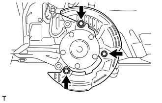
Remove the 3 bolts and the front disc brake dust cover LH.
-
-
DISCONNECT TIE ROD SUB-ASSEMBLY LH
-
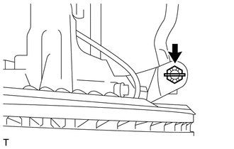
Remove the cotter pin and nut.
-
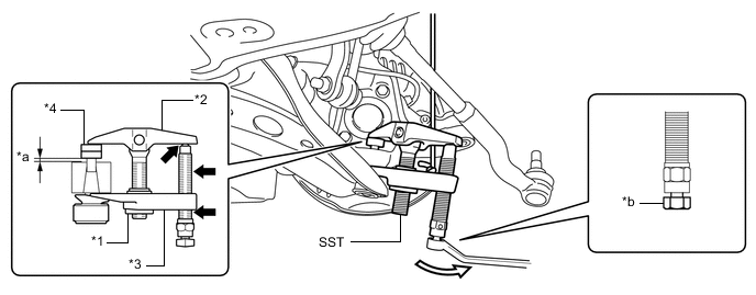
Install the SST (spacer B) to the tie rod assembly.
Note
As SST may get damaged, make sure the space between the tie rod and the spacers is not less than 1 mm (0.0394 in.).
-
Using SST, disconnect the tie rod assembly.
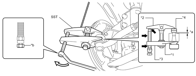
Text in Illustration *1 Nut *2 Body *3 Claw *4 SST (Spacer B) *a 1 mm (0.0394 in.) *b Place a Wrench Here 
Molybdenum Grease 
Turn - SST
- 09960-20010 ( 09961-02010, 09961-02060 )
CAUTION:
Apply the molybdenum grease to the end and threads of the SST bolt.
Note
-
Install SST so that the claw and body are parallel.
-
Make sure to tie the string of SST to the vehicle to prevent SST from dropping.
-
Do not damage the dust cover on the tie rod end sub-assembly.
-
Do not damage the tie-rod end.
-
Do not damage the ball joint dust cover.
-
Do not damage the steering knuckle.
-
-
REMOVE FRONT LOWER SUSPENSION ARM ASSEMBLY LH
-
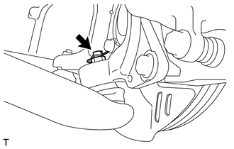
Remove the cotter pin and nut.
-
Install the SST (spacer B) to the front lower suspension arm assembly LH.
Note
As SST may get damaged, make sure the space between the front lower suspension arm assembly LH and the spacers is not less than 1 mm (0.0394 in.).
-
Using SST, disconnect the front lower suspension arm assembly LH.
Text in Illustration *1 Nut *2 Body *3 Claw *4 SST (Spacer B) *a 1 mm (0.0394 in.) *b Place a Wrench Here Molybdenum Grease Turn - SST
- 09960-20010 ( 09961-02010, 09961-02060 )
CAUTION:
Apply the molybdenum grease to the end and threads of SST bolt.
Note
-
Install SST so that the claw and body are parallel.
-
Make sure to tie the string of SST to the vehicle to prevent SST from dropping.
-
Do not damage the dust cover on the front suspension lower arm assembly.
-
Do not damage the front lower arm sub-assembly.
-
Do not damage the front disc brake dust cover.
-
Do not damage the steering knuckle.
-
-
REMOVE STEERING KNUCKLE LH
-
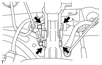
Remove the steering knuckle LH with the 2 bolts and 2 nuts.
Note
When removing the nuts, keep the bolts from rotating.
-