INTAKE MANIFOLD REMOVAL
PROCEDURE
REMOVE RADIATOR ASSEMBLY
REMOVE DIESEL THROTTLE BODY ASSEMBLY
REMOVE ENGINE COVER
DISCONNECT ENGINE WIRE
-
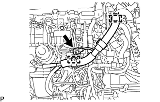
Detach the 2 clamps and disconnect the glow plug controller assembly harness connector.
-
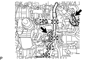
Disconnect the EGR gas temperature sensor connector.
Detach the 6 clamps and disconnect the fuel quantity control valve connector.
-
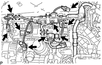
Disconnect the swirl control valve connector.
Disconnect the fuel pressure sensor connector.
Disconnect the engine coolant temperature sensor connector.
Disconnect the generator assembly connector.
Disconnect the camshaft position sensor connector.
Disconnect the turbo pressure sensor assembly connector.
Disconnect the 2 glow plug controller assembly connectors.
Detach the 2 clamps.
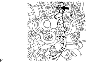
Using a T25 "TORX" socket wrench, remove the screw and disconnect the engine wire.
-
REMOVE ENGINE OIL LEVEL DIPSTICK GUIDE
Remove the engine oil level dipstick.
-
Detach the clamp and disconnect the fuel feed pipe sub-assembly from the engine oil level dipstick guide.
Using a T25 "TORX" socket wrench, remove the bolt and engine oil level dipstick guide.
Remove the O-ring from the engine oil level dipstick guide.
DISCONNECT NO. 2 VACUUM HOSE ASSEMBLY
-
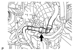
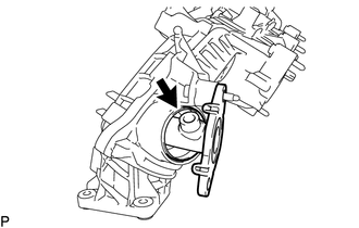
Disconnect the No. 2 vacuum hose assembly from the No. 1 vacuum pipe.
Table 1. Text in Illustration *1
No. 1 Vacuum Pipe
Check that there is no damage or foreign matter on the part of the No. 1 vacuum pipe that contacts the No. 2 vacuum hose assembly connector.
-
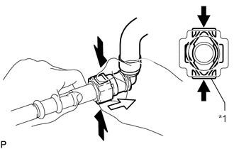
If the No. 2 vacuum hose assembly connector and No. 1 vacuum pipe are stuck together, hold the No. 1 vacuum pipe by hand and push and pull on the No. 2 vacuum hose assembly connector.
Table 2. Text in Illustration *1
Retainer

Pinch

Pull Out
Note:Check for any dirt and foreign matter contamination in the No. 1 vacuum pipe and around the No. 2 vacuum hose assembly connector. Clean if necessary. Foreign matter may damage the O-ring or cause leaks in the seal between the No. 1 vacuum pipe and No. 2 vacuum hose assembly connector.
Do not use any tools to separate the No. 1 vacuum pipe and No. 2 vacuum hose assembly connector.
Check for any dirt and foreign matter on the No. 1 vacuum pipe seal surface. Clean if necessary.
Protect the disconnected part by covering it with a plastic bag and tape after disconnecting the No. 2 vacuum hose assembly.
If the No. 1 vacuum pipe and No. 2 vacuum hose assembly connector are stuck together, pinch the No. 2 vacuum hose assembly connector between your fingers and turn it carefully to free it. Then disconnect the No. 2 vacuum hose assembly.
Check for dirt or mud on the No. 1 vacuum pipe seal surface of the disconnected No. 1 vacuum pipe. Clean if necessary.
To protect the disconnected No. 1 vacuum pipe and No. 2 vacuum hose assembly connector from damage and contamination, cover them with a plastic bag and tape.
-
REMOVE NO. 1 VACUUM PIPE
-
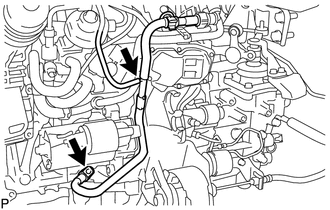
Disconnect the vacuum hose.
Using an E7 "TORX" socket wrench, remove the bolt and No. 1 vacuum pipe from the cylinder block sub-assembly.
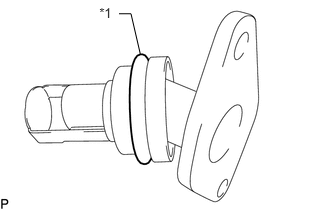
Remove the O-ring from the No. 1 vacuum pipe.
-
REMOVE INTAKE MANIFOLD
-
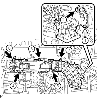
Remove the bolt labeled B and loosen the 6 bolts labeled A in the order shown in the illustration, and then remove the intake manifold.
Table 3. Text in Illustration Bolt A
Bolt B
Tip:The bolts labeled A in the illustration cannot be removed from the intake manifold.
-
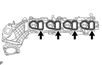
Remove the 4 gaskets from the intake manifold.
Remove the gasket from the No. 2 EGR pipe sub-assembly.
-
REMOVE TURBO PRESSURE SENSOR ASSEMBLY
REMOVE GLOW PLUG CONTROLLER ASSEMBLY
REMOVE EGR GAS TEMPERATURE SENSOR
REMOVE NO. 2 EGR PIPE
-
Remove the No. 2 EGR pipe from the intake manifold.
-
Remove the O-ring from the No. 2 EGR pipe.
Table 4. Text in Illustration *1
O-Ring
-
REMOVE SWIRL CONTROL VALVE
-
Detach the rod from the swirl control valve.
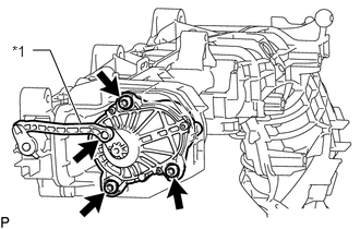
Table 5. Text in Illustration *1
Rod
Remove the 3 bolts and swirl control valve from the intake manifold.
-