CAMSHAFT REMOVAL
PROCEDURE
REMOVE SERVICE PLUG GRIP
REMOVE NO. 1 ENGINE COVER SUB-ASSEMBLY
REMOVE NO. 1 ENGINE UNDER COVER
REMOVE REAR ENGINE UNDER COVER RH
REMOVE FAN AND GENERATOR V BELT
DISCONNECT RADIATOR RESERVOIR ASSEMBLY
REMOVE AIR CLEANER CAP SUB-ASSEMBLY
REMOVE AIR CLEANER FILTER ELEMENT SUB-ASSEMBLY
REMOVE AIR CLEANER CASE SUB-ASSEMBLY
DISCONNECT GROUND WIRE
DISCONNECT ENGINE WIRE
Disconnect the 17 connectors and 2 clamps.
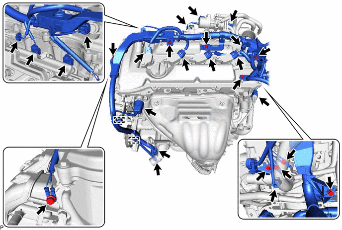
Remove the 7 bolts and 3 nuts and disconnect the engine wire from the engine.
REMOVE IGNITION COIL ASSEMBLY
REMOVE CYLINDER HEAD COVER SUB-ASSEMBLY
SET NO. 1 CYLINDER TO TDC/COMPRESSION
-
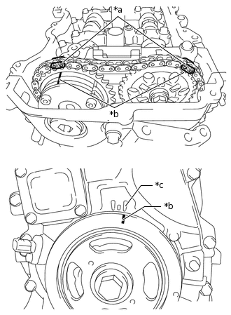
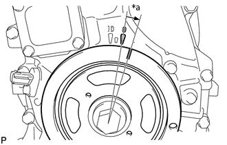
*a
Paint Mark
*b
Timing Mark (Groove)
*c
Timing Mark "0"
Turn the crankshaft until the timing mark (groove) of the crankshaft pulley and the timing mark "0" of the timing chain cover are aligned.
Check that each timing mark of the camshaft timing gear assembly and camshaft timing sprocket are located as shown in the illustration. If not, turn the crankshaft 1 revolution (360°) to align the timing marks as shown in the illustration.
Place paint marks on the chain sub-assembly in alignment with the timing marks on the camshaft timing gear assembly and camshaft timing sprocket.
-
REMOVE TIMING CHAIN COVER PLATE
REMOVE NO. 1 CHAIN TENSIONER ASSEMBLY
-
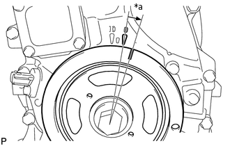
*a
Approximately 10°
Turn the crankshaft approximately 10° clockwise.
-
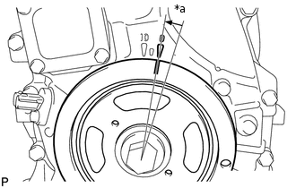
*a
Approximately 10°
Turn the crankshaft approximately 10° counterclockwise.
-
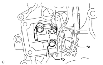
*a
Stopper Plate
*b
Pin
Align the holes of the stopper plate and No. 1 chain tensioner assembly, and insert a pin into the stopper plate hole to lock the No. 1 chain tensioner assembly.
-
*a
Approximately 10°
Turn the crankshaft approximately 10° clockwise.
-
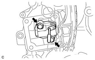
Remove the 2 bolts, No. 1 chain tensioner assembly and gasket.
Note:Make sure not to drop the gasket inside the timing chain cover assembly.
-

*a
Approximately 10°
Turn the crankshaft approximately 10° counterclockwise.
-
REMOVE TIMING CHAIN GUIDE
REMOVE TIMING CHAIN COVER TIGHT PLUG
REMOVE CAMSHAFT TIMING GEAR ASSEMBLY
-
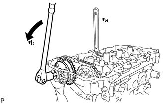
*a
Hold
*b
Turn
Hold the hexagonal portion of the camshaft with a wrench and remove the bolt from the camshaft.
Note:Be careful not to damage the camshaft housing sub-assembly or spark plug tube with the wrench.
-
Separate the camshaft timing gear assembly from the camshaft.
-
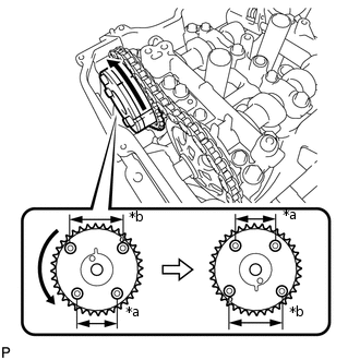
*a
Narrow
*b
Wide
Remove the chain sub-assembly from the camshaft timing gear assembly, and turn the camshaft timing gear assembly approximately 180°.
-
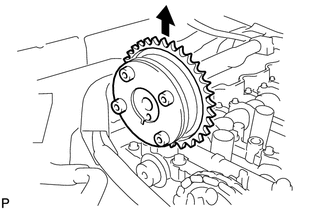
Remove the camshaft timing gear assembly.
Note:Do not disassemble the camshaft timing gear assembly.
-
REMOVE CAMSHAFT BEARING CAP
-
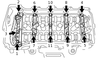
Using several steps, remove the 11 bearing cap bolts in the sequence shown in the illustration.
-
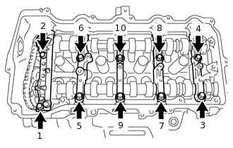
Using several steps, remove the 10 bearing cap bolts in the sequence shown in the illustration.
Remove the 5 camshaft bearing caps.
Tip:Arrange the removed parts in the correct order.
-
REMOVE CAMSHAFT
-
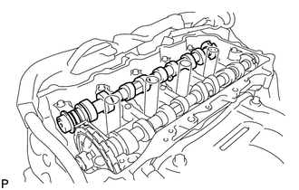
Remove the camshaft from the camshaft housing sub-assembly.
-
REMOVE NO. 2 CAMSHAFT
-
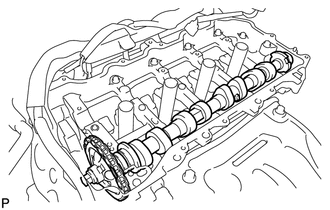
Hold up the chain and remove the No. 2 camshaft from the camshaft housing sub-assembly.
-
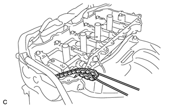
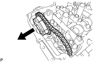
Suspend the chain sub-assembly with a string or equivalent as shown in the illustration.
Note:Be careful not to drop the chain sub-assembly inside the timing chain cover assembly.
-
REMOVE CAMSHAFT TIMING SPROCKET
-
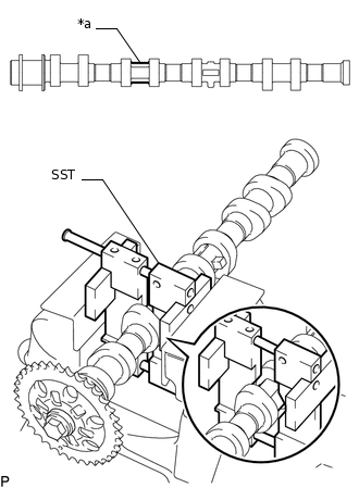
*a
Hexagonal Portion
Using SST, grip the hexagonal portion, and then secure SST and the No. 2 camshaft in a vise as shown in the illustration.
09212-31010
Note:Do not damage the No. 2 camshaft.
Never grip areas other than the hexagonal portion, as this may cause damage.
-
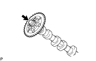
Remove the bolt and camshaft timing sprocket.
Note:Be careful not to damage the No. 2 camshaft and camshaft timing sprocket.
-
REMOVE OIL CONTROL VALVE FILTER
REMOVE NO. 1 CAMSHAFT BEARING
REMOVE NO. 2 CAMSHAFT BEARING