AUDIO AND VISUAL SYSTEM(w/ Multi-display) TERMINALS OF ECU
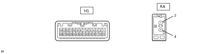
CHECK RADIO RECEIVER ASSEMBLY
Terminal No. (Symbol)
Wiring Color
Terminal Description
Condition
Specified Condition
H1-3 (ILL+) - H1-15 (GND)
G - BR
Illumination signal
Light control switch off
Below 1 V
H1-3 (ILL+) - H1-15 (GND)
G - BR
Illumination signal
Light control switch tail
11 to 14 V
H1-5 (AUXI) - H1-15 (GND)
P - BR
External device connection detection signal
External device connected
Below 1 V
H1-6 (AGND) - Body ground
Shielded - Body ground
Shield ground
Always
Below 1 V
H1-7 (SLD) - Body ground
Shielded - Body ground
Shield ground
Always
Below 1 V
H1-8 (NTSC) - H1-15 (GND)
B - BR
RSE image signal
DVD playing
Waveform synchronized with display signal is output
H1-9 (MI+)
B
MOST communication signal
-
-
H1-10 (SLDI) - Body ground
BR - Body ground
Shield ground
Always
Below 1 V
H1-11 (MO+)
B
MOST communication signal
-
-
H1-12 (WUI) - H1-15 (GND)
L - BR
MOST communication wake up signal
Engine switch on (ACC)
4.5 V or higher
H1-14 (B) - H1-15 (GND)
SB - BR
Battery
Always
11 to 14 V
H1-15 (GND) - Body ground
BR - Body ground
Ground
Always
Below 1 V
H1-17 (ILL-) - H1-15 (GND)
W-B - BR
Illumination (rheostat) signal
Light control switch off
Below 1 V
Light control switch tail
Pulse generation
H1-19 (ARI) - H1-15 (GND)
W - BR
Sound signal (Right)
External device playing (When stereo jack used)
Waveform synchronized with sound is output
H1-20 (ALI) - H1-15 (GND)
B - BR
Sound signal (Left)
External device playing (When stereo jack used)
Waveform synchronized with sound is output
H1-21 (ASGN) - H1-15 (GND)
R - BR
Shield ground
Always
Below 1 V
H1-22 (GND) - H1-15 (GND)
W - BR
Shield ground
Always
Below 1 V
H1-23 (MI-)
W
MOST communication signal
-
-
H1-24 (SLDI) - Body ground
BR - Body ground
Shield ground
Always
Below 1 V
H1-25 (MO-)
W
MOST communication signal
-
-
H1-26 (WUO) - H1-15 (GND)*
L - BR
MOST communication wake up signal
Engine switch on (ACC)
4.5 V or higher
RA-5 (ANT+) - Body ground
BR - Body ground
Power source of antenna
Engine switch on (ACC), radio switch on and AM or FM
11 to 14 V
*: w/ Rear Seat Entertainment System
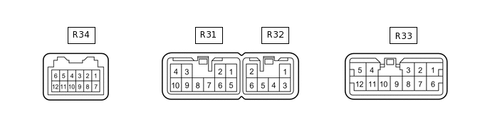
CHECK STEREO COMPONENT AMPLIFIER ASSEMBLY
Terminal No. (Symbol)
Wiring Color
Terminal Description
Condition
Specified Condition
R34-2 (SPD) - R32-2 (GND)
R - BR
Speed signal from combination meter assembly
Engine switch on (IG), drive wheels turned slowly
Pulse generation
R34-3 (WUI) - Body ground
GR - Body ground
MOST communication wake up signal
Engine switch on (ACC)
4.5 V or higher
R34-4 (MI+)
W
MOST communication signal
-
-
R34-5 (SLDI) - Body ground
BR - Body ground
Shield ground
Always
Below 1 V
R34-6 (MO+)
W
MOST communication signal
-
-
R34-9 (WUO) - Body ground
G - Body ground
MOST communication wake up signal
Engine switch on (ACC)
4.5 V or higher
R34-10 (MI-)
B
MOST communication signal
-
-
R34-11 (SLDO) - Body ground
BR - Body ground
Shield ground
Always
Below 1 V
R34-12 (MO-)
B
MOST communication signal
-
-
R34-7 (TMUT) - R32-2 (GND)*
P - BR
Mute signal
Audio system playing
Below 1 V
Emergency call mode
3.5 V or higher
R33-1 (SL+) - R32-2 (GND)
LG - BR
Sound signal
Always
Below 1 V
R33-2 (SR+) - R32-2 (GND)
B - BR
Sound signal
Engine switch on (IG)
2 to 3 V
R33-3 (WFL+) - R32-2 (GND)
P - BR
Sound signal
Engine switch on (IG)
2 to 3 V
R33-4 (RL+) - R32-2 (GND)
B - BR
Sound signal
Audio system playing
Waveform synchronized with sound is output
R33-5 (RR+) - R32-2 (GND)
R - BR
Sound signal
Audio system playing
Waveform synchronized with sound is output
Audio system playing
Waveform synchronized with sound is output
R33-6 (SL-) - R32-2 (GND)
L - BR
Sound signal
Audio system playing
Waveform synchronized with sound is output
R33-11 (RL-) - R32-2 (GND)
Y - BR
Sound signal
Audio system playing
Waveform synchronized with sound is output
R33-7 (SR-) - R32-2 (GND)
Y - BR
Sound signal
Audio system playing
Waveform synchronized with sound is output
R33-8 (WFL-) - R32-2 (GND)
V - BR
Sound signal
Audio system playing
Waveform synchronized with sound is output
R33-9 (WFR-) - R32-2 (GND)
L - BR
Sound signal
Audio system playing
Waveform synchronized with sound is output
R33-10 (WFR+) - R32-2 (GND)
LG - BR
Sound signal
Audio system playing
Waveform synchronized with sound is output
R33-11 (RL-) - R32-2 (GND)
Y - BR
Sound signal
Audio system playing
Waveform synchronized with sound is output
R33-12 (RR-) - R32-2 (GND)
W - BR
Sound signal
Audio system playing
Waveform synchronized with sound is output
R31-1 (WF1+) - R32-2 (GND)
B - BR
Sound signal
Audio system playing
Waveform synchronized with sound is output
R31-2 (WF2+) - R32-2 (GND)
W - BR
Sound signal
Audio system playing
Waveform synchronized with sound is output
R31-3 (FL+) - R32-2 (GND)
P - BR
Sound signal
Audio system playing
Waveform synchronized with sound is output
R31-4 (FR+) - R32-2 (GND)
R - BR
Sound signal
Audio system playing
Waveform synchronized with sound is output
R31-7 (CTR-) - R32-2 (GND)
B - BR
Sound signal
Audio system playing
Waveform synchronized with sound is output
R31-8 (CTR+) - R32-2 (GND)
Y - BR
Sound signal
Audio system playing
Waveform synchronized with sound is output
R31-9 (FL-) - R32-2 (GND)
V - BR
Sound signal
Audio system playing
Waveform synchronized with sound is output
R31-10 (FR-) - R32-2 (GND)
W - BR
Sound signal
Audio system playing
Waveform synchronized with sound is output
R32-1 (+B) - R32-2 (GND)
SB - BR
Battery
Audio system playing
Waveform synchronized with sound is output
R32-2 (GND) - Body ground
BR - Body ground
Ground
Audio system playing
Waveform synchronized with sound is output
R32-3 (+B2) - R32-2 (GND)
SB - BR
Battery
Always
11 to 14 V
R32-6 (GND2) - Body ground
BR - Body ground
Ground
Always
Below 1 V
*: w/ Emergency Call Switch
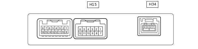
CHECK MULTI-MEDIA INTERFACE ECU
Terminal No. (Symbol)
Wiring Color
Terminal Description
Condition
Specified Condition
H15-1 (USD1) - Body ground
Shielded - Body ground
Shield ground
Always
Below 1 V
H15-2 (URO+) - H15-7 (GND)
W - GR
USB audio system sound signal
USB audio system playing
Waveform synchronized with sound is output
H15-3 (ULO+) - H15-7 (GND)
B - GR
USB audio system sound signal
USB audio system playing
Waveform synchronized with sound is output
H15-4 (UGD1) - H15-7 (GND)
R - GR
USB audio system sound signal
USB audio system playing
Waveform synchronized with sound is output
H15-7 (GND) - Body ground
GR - Body ground
Ground
Always
Below 1 V
H15-9 (TX1+)
V
AVC-LAN communication signal
-
-
H15-10 (TX1-)
P
AVC-LAN communication signal
-
-
H15-11 (ACC) - H15-7 (GND)
SB - GR
Accessory (ON)
Engine switch off
Below 1 V
Engine switch on (ACC)
11 to 14 V
H15-12 (+B) - H15-7 (GND)
LG - GR
Battery
Always
11 to 14 V
H34-1 - Body ground
#
Ground
Always
Below 1 V
H34-2 - H34-1
#
Data signal
USB device or "iPod" connected
-
H34-3 - H34-1
#
Data signal
USB device or "iPod" connected
-
H34-4 - H34-1
#
Battery
Always
5 V
H34-5 - Body ground
Shielded - Body ground
Shield ground
Always
Below 1 V
#: There is no wire color information.
CHECK DISPLAY AND NAVIGATION MODULE DISPLAY (for DVD) (Click hereClick hereClick here)
CHECK DISPLAY AND NAVIGATION MODULE DISPLAY (for HDD) (Click hereClick hereClick here)