ENTRY AND START SYSTEM(for Start Function), Diagnostic DTC:B2285
| DTC Code | DTC Name |
|---|---|
| B2285 | Steering Lock Position Signal Circuit Malfunction |
DESCRIPTION
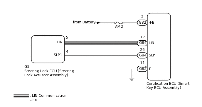
This DTC is stored when the steering lock position signal sent by the steering lock ECU (steering lock actuator assembly) via direct line and the steering lock position signal sent via LIN communication do not match.
When the cable is disconnected and reconnected to the negative (-) battery terminal, the power source mode returns to the state it was in before the cable was disconnected.
DTC No. |
Detection Item |
DTC Detection Condition |
Trouble Area |
DTC Output from |
|---|---|---|---|---|
B2285 |
Steering Lock Position Signal Circuit Malfunction |
The steering lock position signal sent by the steering lock ECU (steering lock actuator assembly) via direct line and the steering lock position signal sent via LIN communication (1-trip detection logic*) do not match. |
|
Disconnect the cable from the negative(-) battery terminal, wait 30 seconds and then reconnect the cable to the negative (-) battery terminal. Wait 40 seconds or more with the engine switch off (with the steering wheel locked), then turn the engine switch on (ACC) (with the steering unlocked) and wait 40 seconds or more. |
*: Only detected while a malfunction is present and the engine switch is on (IG)
Vehicle Condition when Malfunction Detected |
Fail-safe Function when Malfunction Detected |
|---|---|
The engine cannot be started. |
The ECU does not send an engine start request. |
DTC |
Data List Item |
Active Test Item |
|---|---|---|
B2285 |
|
- |
WIRING DIAGRAM
CAUTION / NOTICE / HINT
When using the GTS with the engine switch off to troubleshoot:
Connect the GTS to the DLC3 and turn a courtesy light switch on and off at 1.5 second intervals until communication between the GTS and vehicle begins.
The entry and start system (for Start Function) uses a multiplex communication system (LIN communication system) and the CAN communication system. Inspect the communication function by following How to Proceed with Troubleshooting (Click hereClick here). Troubleshoot the entry and start system (for Start Function) after confirming that the communication systems are functioning properly.
Before replacing the certification ECU (smart key ECU assembly) or steering lock ECU (steering lock actuator assembly), refer to the entry and start system (for Start Function) precaution.
Inspect the fuses of circuits related to this system before performing the following inspection procedure.
After performing repairs, perform the operation that fulfills the DTC output confirmation operation, and then confirm that no DTCs are output again.
PROCEDURE
CHECK FOR DTC (LIN COMMUNICATION SYSTEM)
Check for DTCs.
Body Electrical > Entry&Start > Trouble Codes
Tip:If the steering wheel cannot be locked or unlocked, the engine switch cannot be turned on (IG) and the engine cannot be started.
If LIN communication is not available, the steering wheel cannot be locked or unlocked.
OK
LIN communication system DTC B2785 is not output simultaneously.
Result
Proceed to
OK
NG
READ VALUE USING GTS (STEERING UNLOCK SWITCH)
Connect the GTS to the DLC3.
Turn the engine switch on (IG).
Turn the GTS on.
Enter the following menus: Body Electrical / Power Source Control / Data List.
According to the display on the GTS, read the Data List.
Body Electrical > Power Source Control > Data List
Tester Display
Measurement Item
Range
Normal Condition
Diagnostic Note
Steering Unlock Switch
State of steering unlock sensor signal output from steering lock actuator assembly
ON or OFF
ON: Steering unlocked
OFF: Steering locked
When the shift lever is in P*1 or N*2 and the engine switch is off, if any door is opened or closed, the steering is locked.
When the key is inside the vehicle and the engine switch is turned on (ACC) or on (IG), the steering unlocks.
The engine cannot be started when the steering unlock signal is off.
*1: except Manual Transaxle
*2: for Manual Transaxle
Body Electrical > Power Source Control > Data List
Tester Display
Steering Unlock Switch
Result
Proceed to
Data List item does not change
Data List item changes
CHECK HARNESS AND CONNECTOR (POWER SOURCE)
-
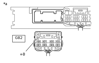
*a
Rear view of wire harness connector
(to Certification ECU (Smart Key ECU Assembly))
Disconnect the G82 certification ECU (smart key ECU assembly) connector.
Measure the voltage according to the value(s) in the table below.
Standard Voltage
Tester Connection
Condition
Specified Condition
G82-2 (+B) - Body ground
Always
11 to 14 V
Result
Proceed to
OK
NG
NG REPAIR OR REPLACE HARNESS OR CONNECTOR IN CIRCUIT CONNECTED TO POWER SOURCE
-
CHECK HARNESS AND CONNECTOR (GROUND)
-
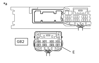
*a
Rear view of wire harness connector
(to Certification ECU (Smart Key ECU Assembly))
Disconnect the G82 certification ECU (smart key ECU assembly) connector.
Measure the resistance according to the value(s) in the table below.
Standard Resistance
Tester Connection
Condition
Specified Condition
G82-11 (E) - Body ground
Always
Below 1 Ω
Result
Proceed to
OK
NG
NG REPAIR OR REPLACE HARNESS OR CONNECTOR
-
INSPECT STEERING LOCK ECU (STEERING LOCK ACTUATOR ASSEMBLY)
-
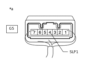
*a
Component with harness connected
(Steering Lock ECU (Steering Lock Actuator Assembly))
Measure the resistance according to the value(s) in the table below.
Standard Resistance
Tester Connection
Condition
Specified Condition
Positive (+) tester probe → G5-4 (SLP1) Negative (-) tester probe → Body ground
Steering locked*
10 kΩ or higher
Steering unlocked*
Below 1 Ω
Tip:*: If any of the doors are opened then closed with the shift lever in P and the engine switch off, the steering wheel will be locked. If the engine switch is then turned on (ACC) or on (IG), the steering wheel will be unlocked.
DTC B2285 may be stored due to a malfunction in the steering lock ECU (steering lock actuator assembly). The steering lock position signal and unlock position signal are sent from the steering lock ECU (steering lock actuator assembly) to the certification ECU (smart key ECU assembly) individually.
Result
Proceed to
OK
NG
-
CHECK HARNESS AND CONNECTOR (CERTIFICATION ECU (SMART KEY ECU ASSEMBLY) - STEERING LOCK ECU (STEERING LOCK ACTUATOR ASSEMBLY))
Disconnect the G84 connector from the certification ECU (smart key ECU assembly).
Disconnect the G5 connector from the steering lock ECU (steering lock actuator assembly).
Measure the resistance according to the value(s) in the table below.
Standard Resistance
Tester Connection
Condition
Specified Condition
G84-26 (SLP) - G5-4 (SLP1)
Always
Below 1 Ω
G84-26 (SLP) or G5-4 (SLP1) - Body ground
10 kΩ or higher
Result
Proceed to
OK
NG
OK REPLACE CERTIFICATION ECU (SMART KEY ECU ASSEMBLY)
NG REPAIR OR REPLACE HARNESS OR CONNECTOR