CAN COMMUNICATION SYSTEM(w/o Central Gateway ECU) PRECAUTION
PRECAUTION FOR DISCONNECTING CABLE FROM NEGATIVE BATTERY TERMINAL
Note:When disconnecting the cable from the negative (-) battery terminal, initialize the following systems after the cable is reconnected.
System Name
See Procedure
Stop and Start System
Simple Intelligent Parking Assist System
Power Door Lock Control System (for Hatchback, Wagon)
IGNITION SWITCH EXPRESSIONS
The type of ignition switch used on this model differs according to the specifications of the vehicle. The expressions listed in the table below are used in this section.
Expression
Ignition Switch (Position)
Engine Switch (Condition)
Ignition Switch off
LOCK
Off
Ignition Switch ACC
ACC
On (ACC)
Ignition Switch ON
ON
On (IG)
Engine Start
START
Start
CAN COMMUNICATION SYSTEM TROUBLESHOOTING
Because the order of diagnosis is important to allow correct diagnosis, make sure to begin troubleshooting using How to Proceed with Troubleshooting when CAN communication system related DTCs are output.
PRECAUTION FOR STEERING SYSTEM HANDLING
Be careful when replacing parts. Incorrect replacement could affect the performance of the steering system and result in hazardous driving.
PRECAUTION FOR SRS AIRBAG SYSTEM HANDLING
This vehicle is equipped with a Supplemental Restraint System (SRS) which includes parts such as airbags for the driver and front passenger. Failure to carry out service operations in the correct sequence could cause unexpected SRS deployment during servicing and may cause a serious accident. Before servicing (including removal or installation of parts, inspection or replacement), be sure to read Precaution for SRS.
BUS LINE REPAIR
-
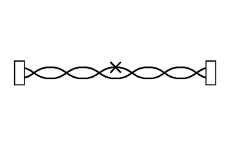
After repairing a bus line with solder, wrap the repaired part with electrical tape.
Note:The CANL bus line and CANH bus line must be installed together at all times.
When installing, make sure that these lines are twisted, because CAN bus lines are likely to be influenced by electrical noise if the bus lines are not twisted.
Leave approximately 80 mm (3.15 in.) loose in the twisted wires around the connector.
When repairing the CAN bus lines, do not change the length of the lines. (Make sure that the length of the CANH bus line and CANL bus line are the same.)
-
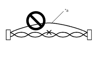
*a
Bypass Wire
Do not use bypass wiring between connectors.
Note:The ability of the twisted bus lines to resist interference will be lost if bypass wiring is used.
Do not use a twisted pair of wires for bypass wiring.
-
CONNECTOR HANDLING
-
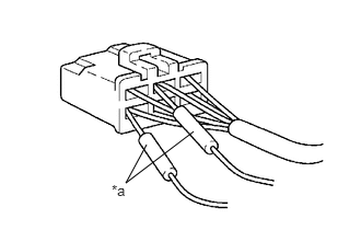
*a
Tester Probe
When checking resistance with a tester, insert the tester probes from the backside (harness side) of the connector.
-
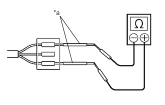
*a
Service Wire
Use service wires to check the connector if it is impossible to check continuity from the rear of the connector.
-