AIR FUEL RATIO SENSOR INSTALLATION
PROCEDURE
INSTALL AIR FUEL RATIO SENSOR
-
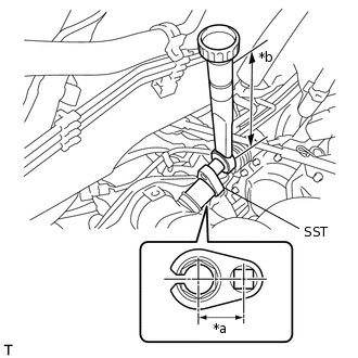
*a
Length of SST 30 mm (1.18 in.)
*b
Length of Torque Wrench 260 mm (10.2 in.)
Using SST, install the air fuel ratio sensor to the exhaust manifold.
09224-00010
without SST [Torque (N*m(kgf*cm, ft.*lbf))]
44 N*m
449 kgf*cm
32 ft.*lbf
with SST [Reading of Torque wrench (N*m(kgf*cm, ft.*lbf))]
39 N*m
398 kgf*cm
29 ft.*lbf
Note:If a component has been dropped or subjected to a strong impact, replace it.
Tip:This torque value is effective when SST is parallel to the torque wrench.
The "with SST" torque value is effective when using SST with a fulcrum length of 30 mm (1.18 in.).
The "with SST" torque value is effective when using a torque wrench with a fulcrum length of 260 mm (10.2 in.).
If using a torque wrench with a different length, or connecting the torque wrench and SST at an angle, refer to the alternate torque values.
Perform "Inspection After Repair" after replacing the air fuel ratio sensor.
Connect the air fuel ratio sensor wire to the wire harness clamp bracket and engage the clamp.
Connect the air fuel ratio sensor connector.
-
INSTALL AIR CLEANER CASE SUB-ASSEMBLY
INSTALL AIR CLEANER CAP SUB-ASSEMBLY
INSPECT FOR EXHAUST GAS LEAK
INSTALL NO. 2 CYLINDER HEAD COVER
INSTALL OUTER COWL TOP PANEL