HEATER ASSEMBLY INSTALLATION
PROCEDURE
INSTALL WATER HOSE AND FUEL HOSE
-
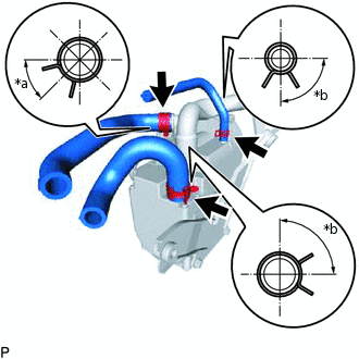
*a
45°
*b
90°
for AD Series Engine:
Connect the 2 water hoses and fuel hose to the heater assembly and engage the 3 clips as shown in the illustration.
-
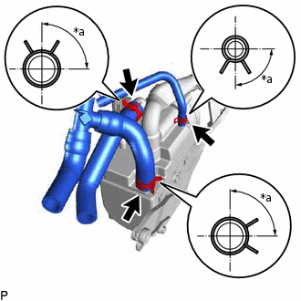
*a
90°
for 2WW:
Connect the 2 water hoses and fuel hose to the heater assembly and engage the 3 clips as shown in the illustration.
-
INSTALL NO. 1 EXHAUST PIPE SUB-ASSEMBLY
Install the 2 new gaskets to the heater assembly.
Install the No. 1 exhaust pipe sub-assembly to the heater assembly with the 2 bolts.
9.8 N*m
100 kgf*cm
87 in.*lbf
INSTALL HEATER AND ACCESSORY ASSEMBLY
-
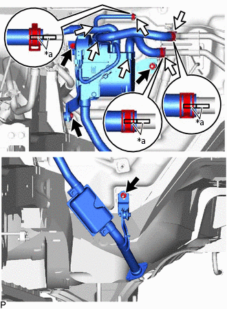
*a
Marking
for AD Series Engine:
Install the heater and accessory assembly with the 2 bolts and nut.
9.8 N*m
100 kgf*cm
87 in.*lbf
Connect the No. 1 exhaust pipe sub-assembly to the body with the nut.
9.8 N*m
100 kgf*cm
87 in.*lbf
Connect each hose and engage the 3 clips as shown in the illustration.
-
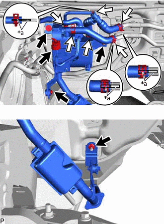
*a
Marking
for 2WW:
Install the heater and accessory assembly with the 2 bolts and nut.
9.8 N*m
100 kgf*cm
87 in.*lbf
Connect the No. 1 exhaust pipe sub-assembly to the body with the nut.
9.8 N*m
100 kgf*cm
87 in.*lbf
Connect each hose and engage the 3 clips as shown in the illustration.
Connect the connector to the heater and accessory assembly.
-
INSTALL NO. 2 EXHAUST PIPE SUB-ASSEMBLY
Install a new gasket to the No. 2 exhaust pipe sub-assembly.
Temporarily install the No. 2 exhaust pipe sub-assembly with the 2 nuts and bolt.
Tighten the 2 nuts and then tighten the bolt.
9.8 N*m
100 kgf*cm
87 in.*lbf
INSTALL NO. 3 COWL TOP PANEL INSULATOR (for 2WW)
INSTALL NO. 1 ENGINE COVER (for 2WW)