VEHICLE STABILITY CONTROL SYSTEM Brake Warning Light Remains ON
| DTC Code | DTC Name |
|---|---|
| Brake Warning Light Remains ON |
DESCRIPTION
The brake warning light comes on when brake fluid is insufficient, the parking brake is applied or EBD control is defective.
If the amount of brake fluid in the master cylinder reservoir is insufficient, DTCs related to the brake fluid are stored.
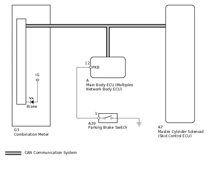
WIRING DIAGRAM
CAUTION / NOTICE / HINT
When replacing the master cylinder solenoid, perform calibration (Click here).
PROCEDURE
CHECK DTC
Check for DTCs.
Result
Result
Proceed to
DTC is not output
A
DTC is output
B
Chassis > ABS/VSC/TRC > Trouble Codes
CHECK CAN COMMUNICATION LINE
Turn the engine switch off.
Connect the intelligent tester to the DLC3.
Turn the engine switch on (IG).
Turn the intelligent tester on.
Select CAN Bus Check from the System Selection Menu screen and follow the prompts on the screen to inspect the CAN bus.
OK
CAN Bus Check indicates no malfunctions in CAN communication.
Result
Result
OK
NG
READ VALUE USING INTELLIGENT TESTER (PARKING BRAKE SW)
Turn the engine switch off.
Connect the intelligent tester to the DLC3.
Turn the engine switch on (IG).
Turn the intelligent tester on.
Enter the following menus: Chassis / ABS/VSC/TRC / Data List.
Chassis > ABS/VSC/TRC > Data List
Tester Display
Measurement Item
Range
Normal Condition
Diagnostic Note
Parking Brake SW
Parking brake switch
ON or OFF
ON: Parking brake applied
OFF: Parking brake released
-
Using the intelligent tester, check the input of the switch operation when the parking brake pedal is operated.
OK
When the parking brake is operated, the display changes as shown above.
Result
Result
OK
NG
NG INSPECT PARKING BRAKE SWITCHClick here
READ VALUE USING INTELLIGENT TESTER (BRAKE WARNING LIGHT)
Turn the engine switch off.
Connect the intelligent tester to the DLC3.
Turn the engine switch on (IG).
Turn the intelligent tester on.
Enter the following menus: Chassis / ABS/VSC/TRC / Data List.
Chassis > ABS/VSC/TRC > Data List
Tester Display
Measurement Item
Range
Normal Condition
Diagnostic Note
Brake Warning Light
Brake warning light
ON or OFF
ON: Warning light on
OFF: Warning light off
-
When performing the Brake Warning Light Active Test, check Brake Warning Light in the Data List.
Chassis > ABS/VSC/TRC > Active Test
Tester Display
Measurement Item
Control Range
Diagnostic Note
Brake Warning Light
Brake warning light
Warning light ON/OFF
Observe the combination meter.
Result
Result
Proceed to
Data List Display
Data List Display when Performing Active Test ON/OFF Operation
ON
Changes between ON and OFF
A
Does not change between ON and OFF
B
OFF
Changes between ON and OFF
A
Does not change between ON and OFF
B
INSPECT PARKING BRAKE SWITCH
Disconnect the A39 parking brake switch connector.
-
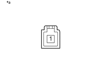
*a
Component without harness connected
(Parking Brake Switch)
Measure the resistance according to the value(s) in the table below.
Standard Resistance
Tester Connection
Switch Condition
Specified Condition
1 - Body ground
Parking brake applied
(Switch pin not pushed in)
Below 1 Ω
Parking brake released
(Switch pin pushed in)
10 kΩ or higher
Result
Result
OK
NG
CHECK HARNESS AND CONNECTOR (PARKING BRAKE SWITCH - MAIN BODY ECU)
Disconnect the A39 parking brake switch connector.
Remove the main body ECU (multiplex network body ECU).
Measure the resistance according to the value(s) in the table below.
Standard Resistance
Tester Connection
Condition
Specified Condition
A39-1 - A-12 (PKB)
Always
Below 1 Ω
A39-1 - Body ground
Always
10 kΩ or higher
Result
Result
OK
NG
OK REPLACE MAIN BODY ECU (MULTIPLEX NETWORK BODY ECU)
NG REPAIR OR REPLACE HARNESS OR CONNECTOR