CHARGING SYSTEM TERMINALS OF ECU
CHECK POWER MANAGEMENT CONTROL ECU (w/ Entry and Start System)
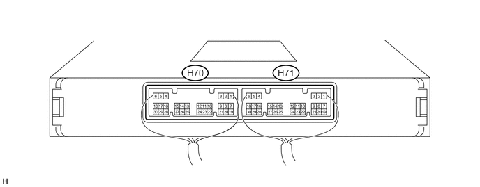
Measure the voltage and resistance according to the value(s) in the table below.
Tip:Perform the measurements with the connectors connected.
Terminal No. (Symbol)
Wiring Color
Terminal Description
Condition
Specified Condition
H71-1 (AM22) - Body ground
L - Body ground
Battery
Always
11 to 14 V
H71-2 (AM21) - Body ground
B - Body ground
Battery
Always
11 to 14 V
H71-6 (GND) - Body ground
W-B - Body ground
Ground
Always
Below 1 Ω
H70-1 (LIN1) - Body ground
V - Body ground
LIN communication signal
Ignition switch off (while LIN communication is stopped)
10 kΩ or higher
H70-23 (VC) - H70-25 (E2)
W - BR
Battery current sensor power supply
Ignition switch ON
4.5 to 5.5 V
H70-28 (THB) - H70-25 (E2)
P - BR
Battery current sensor thermistor signal
Ignition switch ON
(Temperature of thermistor of battery current sensor: -30 to 90°C (-22 to 194°F))
0.5 to 4.5 V
H70-30 (IB) - H70-25 (E2)
B - BR
Battery current sensor signal
Ignition switch ON
(Temperature of thermistor of battery current sensor: -30 to 90°C (-22 to 194°F))
0.5 to 4.5 V
H70-25 (E2) - Body ground
BR - Body ground
Battery current sensor ground
Always
Below 1 Ω
If the result is not as specified, the ECU may have a malfunction.
CHECK POWER MANAGEMENT CONTROL ECU (w/o Entry and Start System)
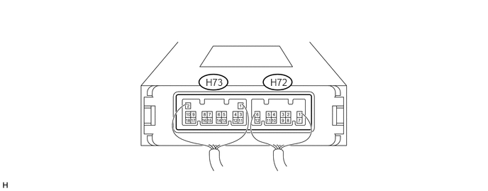
Measure the voltage and resistance according to the value(s) in the table below.
Tip:Perform the measurements with the connectors connected.
Terminal No. (Symbol)
Wiring Color
Terminal Description
Condition
Specified Condition
H72-8 (AM21) - Body ground
B - Body ground
Battery
Always
11 to 14 V
H72-12 (GND) - Body ground
W-B - Body ground
Ground
Always
Below 1 Ω
H73-17 (LIN1) - Body ground
V - Body ground
LIN communication signal
Ignition switch off (while LIN communication is stopped)
10 kΩ or higher
H73-12 (VC) - H73-18 (E2)
W - BR
Battery current sensor power supply
Ignition switch ON
4.5 to 5.5 V
H73-15 (THB) - H73-18 (E2)
P - BR
Battery current sensor thermistor signal
Ignition switch ON
(Temperature of thermistor of battery current sensor: -30 to 90°C (-22 to 194°F))
0.5 to 4.5 V
H73-13 (IB) - H73-18 (E2)
B - BR
Battery current sensor signal
Ignition switch ON
(Temperature of thermistor of battery current sensor: -30 to 90°C (-22 to 194°F))
0.5 to 4.5 V
H73-18 (E2) - Body ground
BR - Body ground
Battery current sensor ground
Always
Below 1 Ω
If the result is not as specified, the ECU may have a malfunction.