HYBRID TRANSMISSION SYSTEM
-
CONSTRUCTION
-
A planetary gear, which is composed of a sun gear, ring gear, pinion gear and planetary carrier, is used for the power split planetary gear.
-
The oil pump drive gear is integrated into the planetary cover for a reduced number of components.
-
The teeth of the oil pump drive gear are cut after being fitted and welded to the input shaft assembly to achieve excellent teeth surface accuracy, helping to enhance quietness.
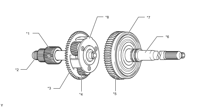
*1 Sun Gear (Generator (MG1)) *2 Input Shaft *3 Planetary Cover
-
Oil Pump Drive Gear (Engine Side)
*4 Pinion Gear *5 Oil Pump Drive Gear (Output Side) *6 Intermediate Shaft *7 Ring Gear (Output) *8 Planetary Carrier (Engine) -
-
-
OPERATION
-
When starting off or driving at low load
-
When starting off and when driving at low load such as when driving at low speeds or on gentle descents, motor (MG2) output is used to drive the vehicle. The engine is stopped and generator (MG1) is controlled to prevent the generation of driving resistance. Therefore, motor (MG2) is free of resistance from the engine drag, contributing to efficient operation.
Figure 1. Power split device operation and collinear lines
-
-
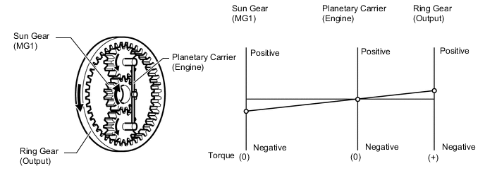
Normal driving
-
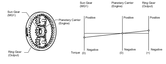
Engine output is split into two paths. One is transmitted to the wheels as driving force. The other is used to drive generator (MG1) to generate power, and this power is then used to drive motor (MG2) to assist engine torque. In this case, the sun gear, planetary carrier and ring gear rotate in a positive direction.
Figure 2. Power split device operation and collinear lines
-
-
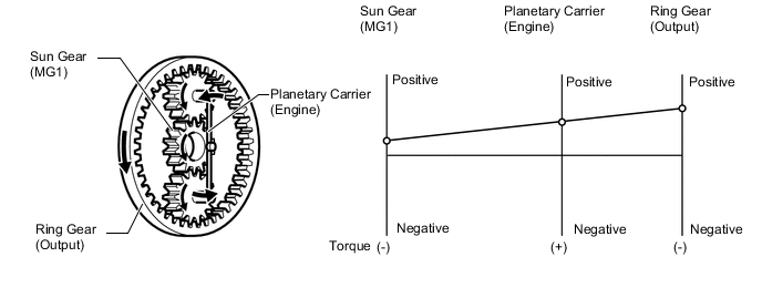
When accelerating
-
When accelerating, engine output is transmitted to the wheels as driving force and at the same time is transmitted to generator (MG1) via the power split device to generate power. This power will then be used to drive motor (MG2) and motor (MG2) output is used to assist acceleration, resulting in high engine speeds. Following normal driving, the power split device may operate as described below.
Figure 3. Power split device operation and collinear lines
Tech Tips
Operation of the gears and the collinear lines are shown as an example of low-speed driving. When accelerating in the high-speed range, the ring gear speed may exceed the sun gear speed.
-
-
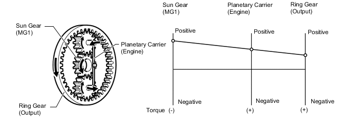
When decelerating or braking
-
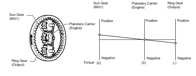
When decelerating and braking, motor (MG2) regenerates electricity using the drive wheels. The engine is stopped and generator (MG1) is controlled to prevent the generation of driving resistance. Therefore, motor (MG2), which is connected to the ring gear (output), is free of resistance from the engine drag, contributing to efficient regeneration.
Figure 4. Power split device operation and collinear lines
-
-
When driving in reverse
-
When driving in reverse, motor (MG2) output is mainly used to drive the vehicle. The engine is stopped and generator (MG1) is controlled to prevent the generation of driving resistance. Therefore, motor (MG2), which is connected to the ring gear (output), is free of resistance from the engine drag, contributing to efficient operation.
Figure 5. Power split device operation and collinear lines
-
-