SEAT HEATER SYSTEM Seat Heater for Front Left Seat does not Operate
DESCRIPTION
When the seat heater switch on air conditioning control assembly is operated, the air conditioning amplifier assembly receives the signal. The air conditioning amplifier assembly receives the signal and operates the front seat heater.
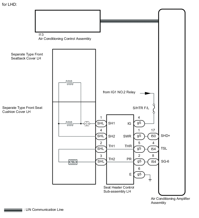
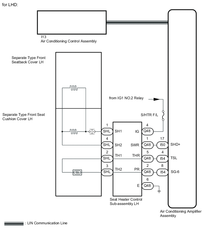
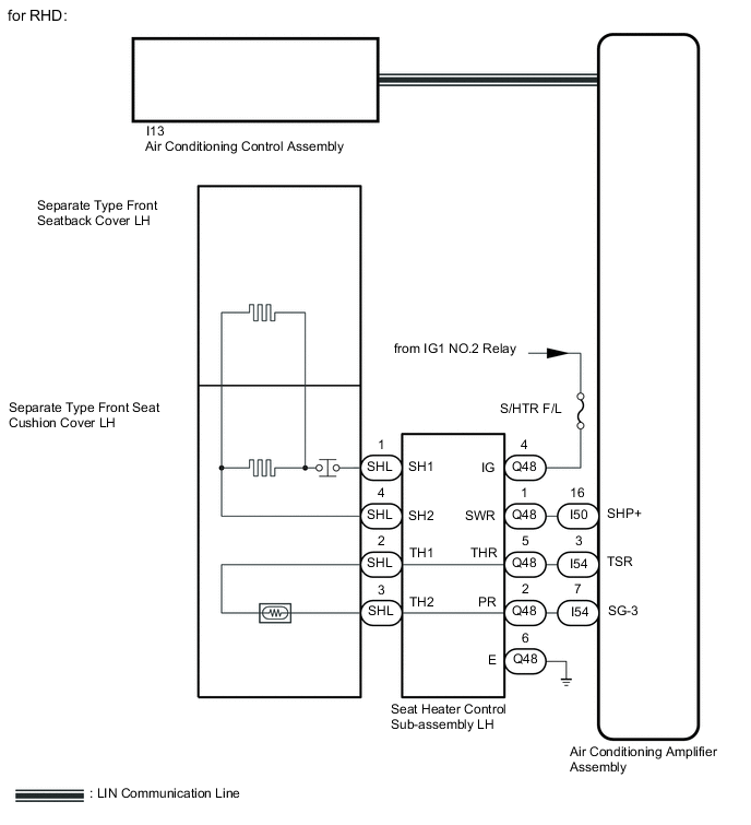
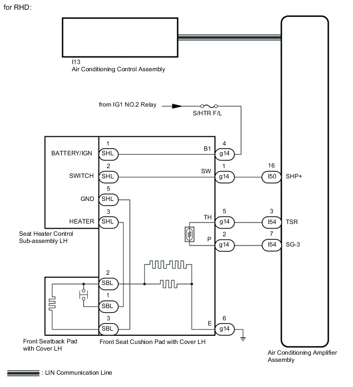
WIRING DIAGRAM
-
for L-Sport Seat Type
-
for Power Seat:

-
for Manual Seat:
-
-
for F-Sport Seat Type

CAUTION / NOTICE / HINT
Note
-
If the battery voltage is low, the seat heater system may not operate. When "High Power Consumption / Partial Limit On AC/Heater Operation" is displayed on the multi-information display in the combination meter assembly, inspect the battery, referring to On-vehicle Inspection for the charging system.
Tech Tips
If the battery voltage is low, "Operation Limitation Control History Count (Level 1)" and "Operation Limitation Control History Count (Level 2) is counted.
-
for 8AR-FTS: Click here
-
for 3ZR-FAE: Click here
-
If the battery voltage is low, the seat heater system may not operate. Refer to Data List for the power steering system.
-
Inspect the fuses for circuits related to this system before performing the following procedure.
-
for Manual Tilt and Manual Telescopic Steering Column: Click here
-
for Power Tilt and Power Telescopic Steering Column: Click here
PROCEDURE
-
READ VALUE USING GTS (FL Seat Heater Temperature)
-
Connect the GTS to the DLC3.
-
Turn the engine switch on (IG).
-
Turn the GTS on.
-
Enter the following menus: Body Electrical / Air Conditioner / Data List.
-
Read the Data List according to the display on the GTS.
Body Electrical > Air Conditioner > Data ListTester Display Measurement Item Range Normal Condition Diagnostic Note FL Seat Heater Temperature Front seat LH heater temperature -29.7°C to 59.55°C Within range from 32 to 43°C (89 to 109°F) Front seat heater is on
Body Electrical > Air Conditioner > Data ListTester Display FL Seat Heater Temperature OK On the GTS screen, the seat heater temperature is as specified in the normal condition column. Result Result Proceed to OK A NG (for L-Sports Seat Type) B NG (for F-Sports Seat Type) C
A 
REPLACE AIR CONDITIONING AMPLIFIER ASSEMBLY Click here
C 
CHECK HARNESS AND CONNECTOR (FRONT SEAT CUSHION PAD WITH COVER LH - BATTERY AND BODY GROUND) Click here
B 
-
-
CHECK HARNESS AND CONNECTOR (SEAT HEATER CONTROL SUB-ASSEMBLY LH - BATTERY AND BODY GROUND)
-
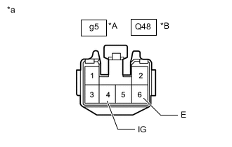
*A for Power Seat *B for Manual Seat *a Front view of wire harness connector
(to Seat Heater Control Sub-assembly LH)
Disconnect the seat heater control sub-assembly LH connector.
-
Measure the resistance according to the value(s) in the table below.
Standard Resistance for Power Seat Tester Connection Condition Specified Condition g5-6 (E) - Body ground Always Below 1 Ω for Manual Seat Tester Connection Condition Specified Condition Q48-6 (E) - Body ground Always Below 1 Ω -
Measure the voltage according to the value(s) in the table below.
Standard Voltage for Power Seat Tester Connection Switch Condition Specified Condition g5-4 (IG) - Body ground Engine switch on (IG) 11 to 14 V g5-4 (IG) - Body ground Engine switch off Below 1 V for Manual Seat Tester Connection Switch Condition Specified Condition Q48-4 (IG) - Body ground Engine switch on (IG) 11 to 14 V Q48-4 (IG) - Body ground Engine switch off Below 1 V Result Proceed to OK NG
NG
REPAIR OR REPLACE HARNESS OR CONNECTOR
OK
-
-
INSPECT SEAT HEATER CONTROL SUB-ASSEMBLY LH
-
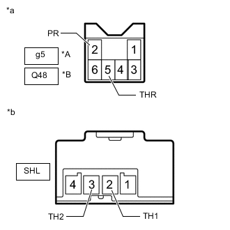
*A for Power Seat *B for Manual Seat *a Seat Heater Control Sub-assembly LH
(to Air Conditioning Amplifier Assembly)
*b Seat Heater Control Sub-assembly LH
(to Separate Type Front Seat Cushion Cover LH)
Disconnect the g5*1 or Q48*2 and SHL seat heater control sub-assembly LH connectors.
-
*1: for Power Seat
-
*2: for Manual Seat
-
-
Measure the resistance according to the value(s) in the table below.
Standard Resistance for Power Seat Tester Connection Condition Specified Condition g5-5 (THR) - SHL-2 (TH1) Always Below 1 Ω g5-5 (THR) or SHL-2 (TH1) - Body ground Always 10 kΩ or higher g5-2 (PR) - SHL-3 (TH2) Always Below 1 Ω g5-2 (PR) or SHL-3 (TH2) - Body ground Always 10 kΩ or higher for Manual Seat Tester Connection Condition Specified Condition Q48-5 (THR) - SHL-2 (TH1) Always Below 1 Ω Q48-5 (THR) or SHL-2 (TH1) - Body ground Always 10 kΩ or higher Q48-2 (PR) - SHL-3 (TH2) Always Below 1 Ω Q48-2 (PR) or SHL-3 (TH2) - Body ground Always 10 kΩ or higher Result Proceed to OK NG
NG
REPLACE SEAT HEATER CONTROL SUB-ASSEMBLY LH for Manual Seat: Click here for Power Seat: Click here
OK
-
-
INSPECT SEPARATE TYPE FRONT SEAT CUSHION COVER LH
-
Remove the separate type front seat cushion cover LH.
-
for Manual Seat: Click here
-
for Power Seat: Click here
-
-
Inspect the separate type front seat cushion cover LH.
-
for Manual Seat: Click here
-
for Power Seat: Click here
Result Proceed to OK NG -
NG
REPLACE SEPARATE TYPE FRONT SEAT CUSHION COVER LH for Manual Seat: Click here for Power Seat: Click here
OK
-
-
INSPECT SEPARATE TYPE FRONT SEATBACK COVER LH
-
Remove the separate type front seatback cover LH.
-
for Manual Seat: Click here
-
for Power Seat: Click here
-
-
Inspect the separate type front seatback cover LH.
-
for Manual Seat: Click here
-
for Power Seat: Click here
Result Proceed to OK NG -
NG
REPLACE SEPARATE TYPE FRONT SEATBACK COVER LH for Manual Seat: Click here for Power Seat: Click here
OK
-
-
CHECK SEAT HEATER CONTROL SUB-ASSEMBLY LH
-
Temporarily replace the seat heater control sub-assembly LH with a new or known good one.
-
for Manual Seat: Click here
-
for Power Seat: Click here
-
-
Check that the seat heater system is operated normally.
OK The seat heater system is operated normally. Result Proceed to OK NG
OK
END (SEAT HEATER CONTROL SUB-ASSEMBLY LH WAS DEFECTIVE)
NG
-
-
CHECK HARNESS AND CONNECTOR (AIR CONDITIONING AMPLIFIER ASSEMBLY - FRONT SEAT CONTROL SUB-ASSEMBLY LH)
-
Disconnect the I50 and I54 air conditioning amplifier assembly connectors.
-
Disconnect the g5*1 or Q48*2 seat heater control sub-assembly LH connector.
-
*1: for Power Seat
-
*2: for Manual Seat
-
-
Measure the resistance according to the value(s) in the table below.
Standard Resistance for LHD (for Power Seat) Tester Connection Condition Specified Condition I50-17 (SHD+) - g5-1 (SWR) Always Below 1 Ω I50-17 (SHD+) or g5-1 (SWR) - Body ground Always 10 kΩ or higher I54-4 (TSL) - g5-5 (THR) Always Below 1 Ω I54-4 (TSL) or g5-5 (THR) - Body ground Always 10 kΩ or higher I54-8 (SG-6) - g5-2 (PR) Always Below 1 Ω I54-8 (SG-6) or g5-2 (PR) - Body ground Always 10 kΩ or higher for LHD (for Manual Seat) Tester Connection Condition Specified Condition I50-17 (SHD+) - Q48-1 (SWR) Always Below 1 Ω I50-17 (SHD+) or Q48-1 (SWR) - Body ground Always 10 kΩ or higher I54-4 (TSL) - Q48-5 (THR) Always Below 1 Ω I54-4 (TSL) or Q48-5 (THR) - Body ground Always 10 kΩ or higher I54-8 (SG-6) - Q48-2 (PR) Always Below 1 Ω I54-8 (SG-6) or Q48-2 (PR) - Body ground Always 10 kΩ or higher for RHD (for Power Seat) Tester Connection Condition Specified Condition I50-16 (SHP+) - g5-1 (SWR) Always Below 1 Ω I50-16 (SHP+) or g5-1 (SWR) - Body ground Always 10 kΩ or higher I54-3 (TSR) - g5-5 (THR) Always Below 1 Ω I54-3 (TSR) or g5-5 (THR) - Body ground Always 10 kΩ or higher I54-7 (SG-3) - g5-2 (PR) Always Below 1 Ω I54-7 (SG-3) or g5-2 (PR) - Body ground Always 10 kΩ or higher for RHD (for Manual Seat) Tester Connection Condition Specified Condition I50-16 (SHP+) - Q48-1 (SWR) Always Below 1 Ω I50-16 (SHP+) or Q48-1 (SWR) - Body ground Always 10 kΩ or higher I54-3 (TSR) - Q48-5 (THR) Always Below 1 Ω I54-3 (TSR) or Q48-5 (THR) - Body ground Always 10 kΩ or higher I54-7 (SG-3) - Q48-2 (PR) Always Below 1 Ω I54-7 (SG-3) or Q48-2 (PR) - Body ground Always 10 kΩ or higher Result Proceed to OK NG
NG
REPAIR OR REPLACE HARNESS OR CONNECTOR
OK
-
-
CHECK AIR CONDITIONING AMPLIFIER ASSEMBLY
-
Temporarily replace the air conditioning amplifier assembly with a new or known good one.
-
Check that the seat heater system is operated normally.
OK The seat heater system is operated normally. Result Proceed to OK NG
OK
END (AIR CONDITIONING AMPLIFIER ASSEMBLY WAS DEFECTIVE)
NG
REPLACE AIR CONDITIONING CONTROL ASSEMBLY Click here
-
-
CHECK HARNESS AND CONNECTOR (FRONT SEAT CUSHION PAD WITH COVER LH - BATTERY AND BODY GROUND)
-
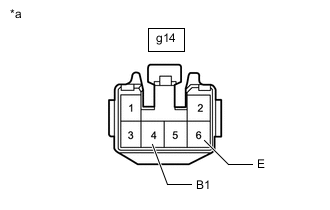
*a Front view of wire harness connector
(to Front Seat Cushion Pad with Cover LH)
Disconnect the front seat cushion pad with cover LH connector.
-
Measure the resistance according to the value(s) in the table below.
Standard Resistance Tester Connection Condition Specified Condition g14-6 (E) - Body ground Always Below 1 Ω -
Measure the voltage according to the value(s) in the table below.
Standard Voltage Tester Connection Switch Condition Specified Condition g14-4 (B1) - Body ground Engine switch on (IG) 11 to 14 V g14-4 (B1) - Body ground Engine switch off Below 1 V Result Proceed to OK NG
NG
REPAIR OR REPLACE HARNESS OR CONNECTOR
OK
-
-
INSPECT FRONT SEAT CUSHION PAD WITH COVER LH
-
Remove the front seat cushion pad with cover LH.
-
Inspect the front seat cushion pad with cover LH.
Result Proceed to OK NG
NG
REPLACE FRONT SEAT CUSHION PAD WITH COVER LH Click here
OK
-
-
INSPECT FRONT SEATBACK PAD WITH COVER LH
-
Remove the front seatback pad with cover LH.
-
Inspect the front seatback pad with cover LH.
Result Proceed to OK NG
NG
REPLACE FRONT SEATBACK PAD WITH COVER LH Click here
OK
-
-
CHECK SEAT HEATER CONTROL SUB-ASSEMBLY LH
-
Temporarily replace the seat heater control sub-assembly LH with a new or known good one.
-
Check that the seat heater system is operated normally.
OK The seat heater system is operated normally. Result Proceed to OK NG
OK
END (SEAT HEATER CONTROL SUB-ASSEMBLY RH WAS DEFECTIVE)
NG
-
-
CHECK HARNESS AND CONNECTOR (AIR CONDITIONING AMPLIFIER ASSEMBLY - FRONT SEAT CUSHION PAD WITH COVER LH)
-
Disconnect the I50 and I54 air conditioning amplifier assembly connectors.
-
Disconnect the g14 front seat cushion pad with cover LH connector.
-
Measure the resistance according to the value(s) in the table below.
Standard Resistance for LHD Tester Connection Condition Specified Condition I50-17 (SHD+) - g14-1 (SW) Always Below 1 Ω I50-17 (SHD+) or g14-1 (SW) - Body ground Always 10 kΩ or higher I54-4 (TSL) - g14-5 (TH) Always Below 1 Ω I54-4 (TSL) or g14-5 (TH) - Body ground Always 10 kΩ or higher I54-8 (SG-6) - g14-2 (P) Always Below 1 Ω I54-8 (SG-6) or g14-2 (P) - Body ground Always 10 kΩ or higher for RHD Tester Connection Condition Specified Condition I50-16 (SHP+) - g14-1 (SW) Always Below 1 Ω I50-16 (SHP+) or g14-1 (SW) - Body ground Always 10 kΩ or higher I54-3 (TSR) - g14-5 (TH) Always Below 1 Ω I54-3 (TSR) or g14-5 (TH) - Body ground Always 10 kΩ or higher I54-7 (SG-3) - g14-2 (P) Always Below 1 Ω I54-7 (SG-3) or g14-2 (P) - Body ground Always 10 kΩ or higher Result Proceed to OK NG
OK
GO TO STEP 8 Click here
NG
REPAIR OR REPLACE HARNESS OR CONNECTOR
-