PURGE VALVE INSTALLATION
PROCEDURE
INSTALL PURGE VALVE (PURGE VSV)
Install the purge valve (purge VSV) to the cylinder head cover sub-assembly with the bolt.
8.8 N*m
90 kgf*cm
78 in.*lbf
Connect the No. 1 fuel vapor feed hose and No. 2 fuel vapor feed hose to the purge valve (purge VSV) and slide the 2 clips to secure them.
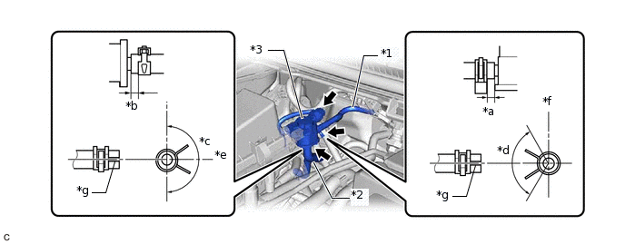
*1
No. 1 Fuel Vapor Feed Hose
*2
No. 2 Fuel Vapor Feed Hose
*3
Purge Valve (Purge VSV)
-
-
*a
2 to 7 mm (0.0787 to 0.276 in.)
*b
2 to 5 mm (0.0787 to 0.197 in.)
*c
180°
*d
120°
*e
Rear
*f
Upper
*g
Paint Mark
-
-
Tip:Engage the clip within the area shown in the illustration.
Connect the purge valve (purge VSV) connector.