STARTER(w/ Stop And Start System) REMOVAL
CAUTION / NOTICE / HINT
The necessary procedures (adjustment, calibration, initialization or registration) that must be performed after parts are removed, installed or replaced during the starter assembly removal/installation are shown below.
| Replacement Part or Procedure | Necessary Procedures | Effect/Inoperative when not Performed | Link |
|---|---|---|---|
| Battery terminal is disconnected/reconnected | Memorize steering angle neutral point | Pre-crash safety system | |
| Drive the vehicle until stop and start control is permitted (approximately 5 to 60 minutes) | Stop and start system | ||
w/ Stop and Start System: Note When the starter assembly is replaced, "ST NO. 1 relay" and "ST NO. 2 relay" must be also replaced. |
Clear the number of starter operations |
PROCEDURE
-
PRECAUTION
Note
After turning the ignition switch off, waiting time may be required before disconnecting the cable from the battery terminal. Therefore, make sure to read the disconnecting the cable from the battery terminal notice before proceeding with work.
-
DISCONNECT CABLE FROM NEGATIVE BATTERY TERMINAL
Note
When disconnecting the cable, some systems need to be initialized after the cable is reconnected.
-
REMOVE FRONT FENDER SEAL LH
-
Remove the 6 clips and front fender seal LH.
-
-
REMOVE NO. 1 ENGINE UNDER COVER ASSEMBLY
-
REMOVE NO. 2 ENGINE UNDER COVER
-
REMOVE FRONT PROPELLER SHAFT ASSEMBLY (for 4WD)
-
DISCONNECT FRONT DIFFERENTIAL CARRIER ASSEMBLY (for 4WD)
-
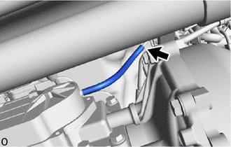
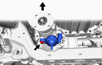
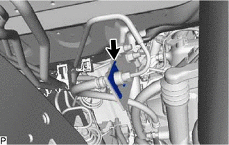
Disconnect the breather hose from the differential breather tube bracket.
-
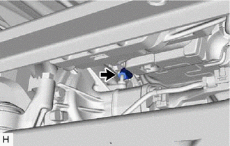
Remove the bolt and disconnect the differential breather tube bracket.
-
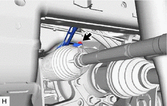
Disconnect the hose from the front differential union.
-
Disconnect the differential oil temperature sensor connector.
-
Remove the bolt and disconnect the wire harness.
-
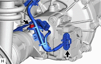
Disconnect the differential motor actuator connector.
-
Remove the bolt and disconnect the wire harness.
-
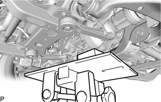
Support the front differential carrier assembly with a transmission jack.
-
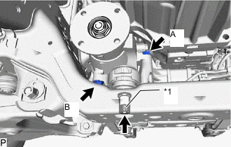
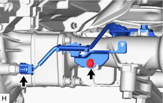
*1 Differential Mount Nut Using a 17 mm ball joint lock nut wrench, loosen bolt A and bolt B.
-
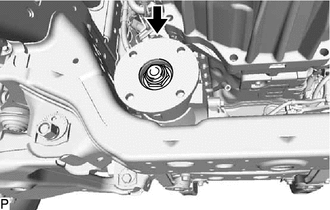
Using a 12 mm hexagon socket wrench, remove the differential mount nut.
-
Remove bolt A.
-
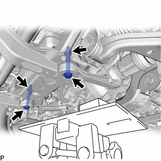
Remove the 2 front mounting bolts, 2 lower differential mount stoppers and 2 nuts from the front differential carrier assembly.
-
Lift up the front differential carrier assembly and remove bolt B and the front No. 3 differential support.
-
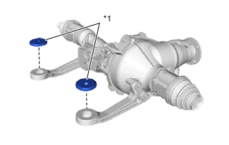
*1 Upper Differential Mount Stopper Remove the 2 upper differential mount stoppers from the front differential carrier assembly.
-
Lower the front differential carrier assembly as shown in the illustration.
-
-
REMOVE CLUTCH FLEXIBLE HOSE BRACKET (for Manual Transmission)
-
Remove the clip from the clutch flexible hose bracket.
-
Remove the 2 nuts and clutch flexible hose bracket.
-
-
DISCONNECT CLUTCH RELEASE CYLINDER ASSEMBLY (for Manual Transmission)
-
REMOVE UREA TANK SUB-ASSEMBLY (w/ Urea SCR System)
-
REMOVE NO. 2 UREA TANK FILLER PIPE SUPPORT (w/ Urea SCR System)
-
Remove the bolt and No. 2 urea tank filler pipe support.
-
-
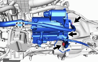
REMOVE STARTER ASSEMBLY
-
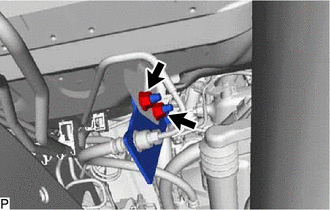
Disconnect the 2 starter connectors.
-
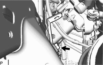
Remove the nut and disconnect the starter wire.
-
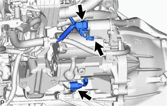
for Automatic Transmission:
-
Detach the clamp.
-
Remove the nut, 3 bolts and starter assembly and disconnect the ground cable.
-
-
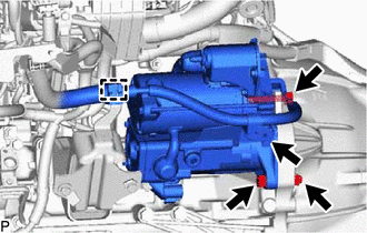
for Manual Transmission:
-
Detach the clamp.
-
Remove the 3 bolts and starter assembly and disconnect the ground cable.
-
-