BRAKE CONTROL SYSTEM
-
FUNCTION OF MAIN COMPONENTS
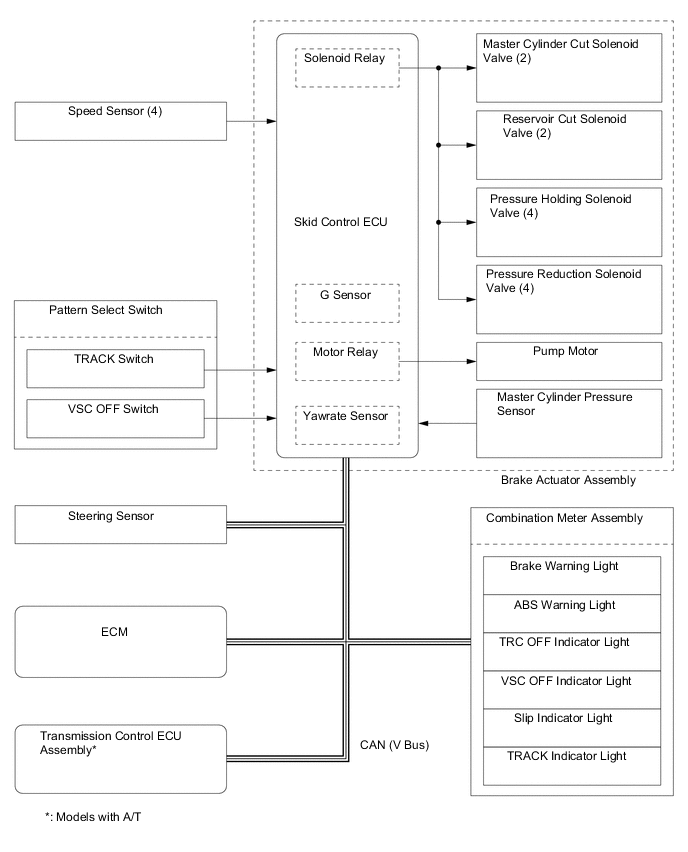
Component Function Combination Meter Assembly Brake System Warning Light
-
Illuminates to alert the driver when the skid control ECU detects a malfunction in the EBD or brake system.
-
Illuminates to alert the driver when the brake fluid level is low.
-
Illuminates to inform the driver of the parking brake condition.
ABS Warning Light Illuminates to alert the driver when the skid control ECU detects a malfunction in the ABS. Slip Indicator Light
-
Blinks to inform the driver when the TRC and VSC.
-
Illuminates to alert the driver when the skid control ECU detects a malfunction in the TRC or VSC.
VSC OFF Indicator Light
-
Illuminates when the VSC OFF switch (pattern select switch assembly) is pressed for about three seconds to select VSC OFF Mode.*1
-
Illuminates when TRACK Mode is selected.
TRACK Indicator Light Illuminates when TRACK Mode is selected. TRC OFF Indicator Light
-
Illuminates when the VSC OFF switch (pattern select switch assembly) is pressed briefly to select TRC OFF Mode.*2
-
Illuminates when the VSC OFF switch (pattern select switch assembly) is pressed for about three seconds to select TRC OFF Mode.*1
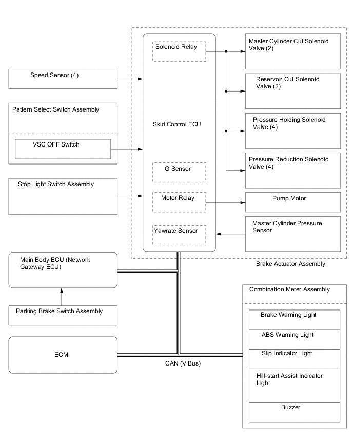
Hill Start Assist Control Indicator Light The light is on when the hill-start assist control function is on and flashes during operation. During a failure, a buzzer sounds and the light switches off at the same time. Buzzer When hill-start assist control fails while the hill-start assist control function is on, an alarm sounds to warn the driver. Master Warning Light*3
Illuminates when the warning message is displayed in the multi-information display. Multi-information Display*3
Shows a warning message to alert the driver, such as when the vehicle is being driven with the parking brake still engaged. VSC OFF Switch (Pattern Select Switch Assembly) Enables the driver to select "Normal Mode", "TRC OFF Mode", "VSC OFF Mode" or "VSC/TRC OFF Mode". TRACK Switch (Pattern Select Switch Assembly) Enables the driver to select Normal Mode or TRACK Mode. Stop Light Switch Assembly Detects the brake pedal depressing signal. Steering Sensor Detects the direction and angle of the steering wheel. Front and Rear Speed Sensors Detects the wheel speed of each of the 4 wheels. Brake Actuator Assembly Changes the fluid path based on the signals from the skid control ECU during the operation of the brake control system functions, in order to control the fluid pressure applied to the wheel cylinders. Master Cylinder Pressure Sensor
(Built into Brake Actuator Assembly)
Detects the master cylinder pressure. Skid Control ECU
-
Judges the vehicle driving condition based on the signals from each sensor, and sends the brake control signals to the brake actuator.
-
Sends an emergency braking signal request signal to the main body ECU (network gateway ECU) based on signals received from each sensor and the operation of the brake pedal.
Yawrate Sensor
(with Built-in Skid Control ECU)
Detects vehicle turning angle velocity and front and rear, left and right acceleration. ECM Based on the signals received from the skid control ECU, controls the engine output. Parking Brake Switch Assembly Outputs a parking brake operation signal to the main body ECU (network gateway ECU). Main Body ECU (Network Gateway ECU) Sends the parking brake switch signal to the main body ECU (network gateway ECU). Clock Assembly Hazard Warning Signal Switch Transmits a hazard warning light on/off request signal to the main body ECU (network gateway ECU). Tech Tips
*1: If the VSC OFF switch (pattern select switch assembly) is pressed for about three seconds, VSC and TRC turn off, and the VSC OFF indicator light and TRC OFF indicator light illuminate simultaneously.
*2: If the vehicle speed exceeds about 50 km/h (31.1 mph) while in TRC OFF mode, TRC automatically turns on, and the TRC OFF indicator light turns off.
*3: Models with TFT LCD type multi-information display
-
-
SYSTEM CONTROL
Control Outline Anti-lock Brake System (ABS) The ABS helps prevent the wheels from locking when the brakes are applied firmly or when braking on a slippery surface. Electronic Brake Force Distribution (EBD) The EBD control utilizes ABS, achieving proper brake force distribution between the front and rear wheels in accordance with the driving conditions. Brake Assist
-
The primary purpose of brake assist is to provide an auxiliary brake force to assist a driver who cannot generate a large brake force during emergency braking, thus helping enhance the vehicle's braking performance.
-
If the skid control ECU judges that the brake pedal force applied by the driver is not sufficient to enhance adequate braking force, brake assist is used to enhance the braking force.
Traction Control (TRC) The TRC helps restrain the slippage of the drive wheels if the driver depresses the accelerator pedal excessively when starting off or while accelerating on a slippery surface. Limited Slip Differential (LSD) Function The LSD function detects a difference in rotation speeds between the left and right drive wheels. If there is a difference in rotation speeds between them, this function applies brake to the drive wheel that rotates faster than the other using pressurization function of the VSC to minimize the difference. Vehicle Stability Control (VSC) The VSC helps restrain sideways slippage of the vehicle during a strong front wheel skid or strong rear wheel skid, which may occur while cornering. Hill-start Assist Control*1
When starting uphill, this control maintains the brake hydraulic pressure on all 4 wheels, in order to momentarily prevent the vehicle from descending backward. Emergency Brake Signal*2
In the case of emergency braking, the emergency brake signal flashers the hazard warning lights to alert drivers in following vehicles. Tech Tips
*1: Hill-start assist control is off by default.
*2: Except Models for Korea
-
Anti-lock Brake System (ABS)
-
The ABS helps prevent the wheels from locking during sudden braking or braking on a slippery surface. This provides the proper braking force when the vehicle slips, thus ensuring vehicle stability and excellent braking performance.
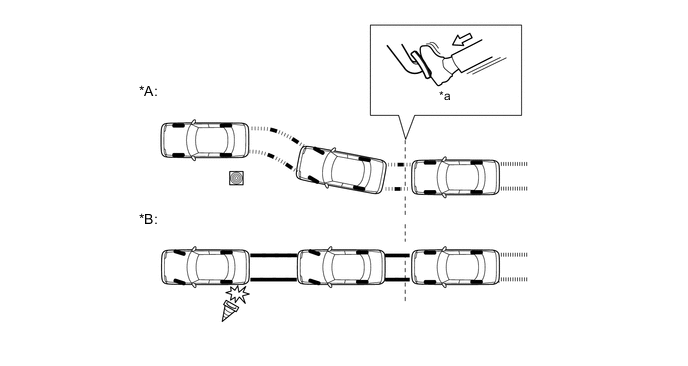
Text in Illustration (Illustration Provides Conceptual Image:) *A Models with ABS *B Models without ABS *a Brake Operation - -
-
-
Electronic Brake Force Distribution (EBD)
-
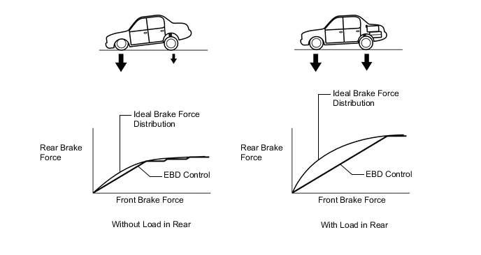
This function controls the brake force that acts on the rear wheels in accordance with the changes in the vehicle conditions such as load factors or deceleration, in order to enhance excellent braking performance.
-
-
Brake Assist
-
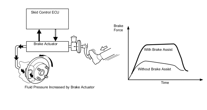
During the brake assist, the skid control ECU calculates the speed and the amount of the brake pedal application based on the signals from the master cylinder pressure sensor and then determines the intention of the driver to make an emergency brake application. If the skid control ECU determines that the driver intends to make an emergency brake application, this function activates the brake actuator to increase the brake fluid pressure, which increases the brake force.
-
-
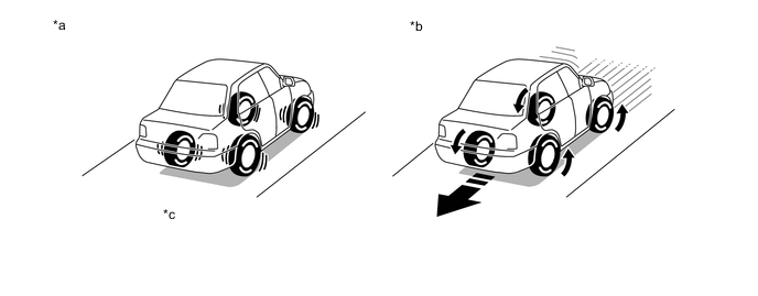
Traction Control (TRC)
-
The TRC helps prevent the drive wheels from slipping if the driver depresses the accelerator pedal excessively when starting off or accelerating on a slippery surface. Simultaneously with the hydraulic brake control of the drive wheels, the skid control ECU makes a request to the ECM to effect engine output control. This produces the drive force that suits the driving conditions, in order to enhance the proper start-off acceleration.
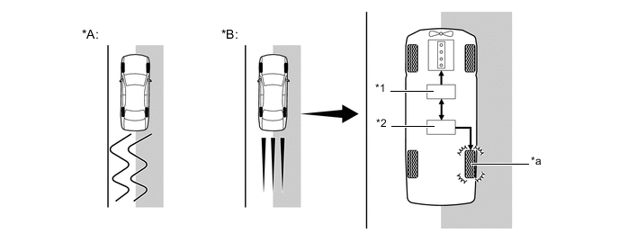
Text in Illustration (Driving on Road with Differing Surface Friction Characteristics:) *A Models without TRC *B Models with TRC *1 ECM
- Engine Output Control
*2 Brake Actuator Assembly
- Hydraulic Brake Control
*a Brake Slipping Drive Wheel - - 
Slippery Surface - -
-
-
Limited Slip Differential (LSD) Function
-
The LSD function detects a difference in rotation speeds between the left and right drive wheels. If there is a difference in rotation speeds between them, this function applies brake to the drive wheel that rotates faster than the other using pressurization function of the VSC*to minimize the difference.
-
This function makes it possible to start and accelerate the vehicle stably.
Tech Tips
*: In the case of an A/T vehicle, brake LSD function is maintained regardless of whether VSC Mode is on or off, but the control parameters change. In the case of a M/T vehicle, this function is stopped VSC Mode is off. This enabled traveling in the original base state.
-
-
Vehicle Stability Control (VSC)
-
The following are 2 examples that can be considered circumstances in which the tires exceed their lateral grip limit. The VSC is designed to help control the vehicle behavior by controlling the engine output and the brakes of each wheel when the vehicle is under one of the conditions indicated below:
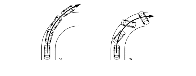
Text in Illustration *a Front Wheel Skid Tendency (Understeer)
- When the front wheels lose grip in relation to the rear wheel
*b Rear Wheel Skid Tendency (Oversteer)
- When the rear wheels lose grip in relation to the front wheels
-
The vehicle's sideways skid tendency is determined by the skid control computer based on the target yaw rate and actual vehicle yaw rate values.
-
Whether or not the vehicle is experiencing a front wheel skid is determined by the difference between the target yaw rate and the vehicle's actual yaw rate. When the vehicle's actual yaw rate is smaller than the target yaw rate (which is determined based on the vehicle speed and steering angle) that should be generated when the driver operates the steering wheel, it means the vehicle is making a turn at a greater angle than the target locus of travel. Thus, the skid control ECU determines that there is a large front wheel skid tendency.
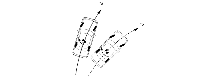
Text in Illustration *a Actual Locus of Travel (Actual Yaw Rate) *b Locus of Travel Based on Target Yaw Rate -
Whether or not the vehicle is experiencing a rear wheel skid is determined by the values of the vehicle's slip angle and the vehicle's slip angular velocity (time-dependent changes in the vehicle's slip angle). When the vehicle's slip angle is large, and the slip angular velocity is also large, the skid control ECU determines that the vehicle has a large rear wheel skid tendency.

Text in Illustration *a Travel Direction of Vehicle's Center of Gravity *b Movement of Vehicle 
Slip Angle - - -
When the skid control ECU determines that the vehicle is exhibiting a tendency to experience a front wheel skid or a rear wheel skid, it decreases the engine output and applies the brakes of each wheel to control the vehicle's yaw moment. The basic operation of the VSC is described below. However, the control method differs depending on the vehicle's characteristics and driving conditions.
-
When the skid control ECU determines that there is a front wheel skid tendency, it applies the brake on the rear wheel on the inside of the turn in accordance with the extent of the skid tendency in order to help restrain the front wheel from skidding.

Text in Illustration Control Moment 
Brake Force -
When the skid control ECU determines that there is a large rear wheel skid tendency, it takes countermeasures in accordance with the extent of that tendency. It applies the brakes of the front wheel of the outer circle of the turn, and generates an outward moment of inertia in the vehicle, in order to restrain the rear wheel skid tendency. Along with the reduction in the vehicle speed caused by the braking force, excellent vehicle stability is enhanced. In some cases, the skid control ECU applies the brake of the rear wheels, as necessary.

Text in Illustration Control Moment Brake Force
-
-
Hill-start Assist Control
-
When the vehicle starts off on a steep or slippery hill, it may start to descend backward while the driver switches from the brake pedal to the accelerator pedal, thus making it difficult for the vehicle to start off. To prevent this from occurring, the hill-start assist control temporarily (approximately 2 seconds at the maximum) applies the brakes to the 4 wheels in order to prevent the vehicle from descending backward.
-
Without the hill-start assist control, the driver must quickly and precisely switch from the brake pedal to the accelerator pedal. With the hill-start assist control, however, the driver a start off easily and operate the pedal in a relaxed manner, because the hill-start assist control prevents the vehicle from descending backward.
Text in Illustration *a Models with Hill-start Assist Control *b Models without Hill-start Assist Control *c Prevents vehicle from descending backward by controlling brakes. - - -
Hill-start assist control is off by default. It can be switched on through a user operation.
-
To enable the hill-start assist control function, perform the following procedure.
Step Method of Operation 1 Park the vehicle in a stable location in which the ground is flat and solid. 2 Make sure that the parking brake is engaged securely. 3 Set the ignition switch off. 4 Start the engine, and then make sure that the ABS warning and slip indicator lights are off. 5 Press and hold the VSC OFF switch. (The VSC OFF indicator light switches on.) Continue pressing until the VSC OFF indicator light switches off (after about 30 seconds). 6 After the VSC OFF indicator light switches off, release the switch within 5 seconds. 7 After releasing the switch, press the VSC OFF switch again within 2 seconds. The hill-start assist control indicator light switches on, and then the hill-start assist control indicator light switches off. 8 Set the ignition switch off. If the engine is started again, the hill-start assist control indicator light stays on, indicating that the hill-start assist control function is on. Tech Tips
-
When the hill-start assist control function is on, the hill-start assist control indicator light is on.
-
If the hill-start assist control function is switched on once by the driver, the hill-start assist control function stays on even if the ignition switch off.
-
When the vehicle is stopped on a hill road, and the hill-start assist control function operation conditions are satisfied, the hill-start assist control indicator light flashes. When the vehicle starts from a stop, the driver is notified that the brake is being maintained temporarily.
-
If the brake is released and an accelerator pedal operation is recognized, the retention of brake fluid pressure is released, and the vehicle can depart. (The brake fluid pressure is released about 2 seconds after the brake is released.)
-
When a failure has occurred that disables maintenance of the hill-start assist control function while the function is on, the hill-start assist control indicator light switches off and a buzzer sounds at the same time to notify the driver.
-
The hill-start assist control indicator light is off when the hill-start assist control function is on.
-
-
Procedure to switch off the hill-start assist control function
Step Method of Operation 1 Park the vehicle in a stable location in which the ground is flat and solid. 2 Make sure that the parking brake is engaged securely. 3 Set the ignition switch off. 4 Start the engine, and then make sure that the ABS warning and slip indicator lights are off. And make sure that the hill-start assist control indicator light are on. 5 Press and hold the VSC OFF switch. (The VSC OFF indicator light switches on.) Continue pressing until the VSC OFF indicator light switches off (after about 30 seconds). 6 After the VSC OFF indicator light switches off, release the switch within 5 seconds. 7 After releasing the switch, press the VSC OFF switch again within 2 seconds. The hill-start assist control indicator light switches off (2 seconds), and then the hill-start assist control indicator light switches on. 8 Set the ignition switch off. If the engine is started again, the hill-start assist control indicator light off, indicating that the hill-start assist control function is off. Tech Tips
-
The hill-start assist control indicator light is off when the hill-start assist control function is off.
-
-
Hill-start Assist Control Activation Conditions
-
The skid control ECU judges if the vehicle is on an uphill incline based on signals from the deceleration sensor, and activates hill-start assist control when the vehicle is started with all of the following conditions met.
Hill-start Assist Control Activation Conditions
-
The shift lever is in any position other than P or N (Forward climbing and backward climbing).*1
-
The shift lever is in a position other than R when starting off forward on an upward incline or in R when starting off backward on an upward incline.*2
-
The vehicle is at a standstill.
-
The accelerator pedal is not depressed.
-
The parking brake is released.
-
There are no errors with the VSC system.
-
The hill-start assist control indicator light is on.
-
Hill-start assist control is set to ON.
-
When the ignition switch ON.
-
The clutch is not engaged.*2
Tech Tips
*1: Models with A/T
*2: Models with M/T
-
-
-
Hill-start Assist Control Cancelation Conditions
-
If any of the following conditions is met, hill-start assist control operation is canceled.
Hill-start Assist Control Cancelation Conditions
-
The shift lever is moved to P or N.*1
-
The shift lever is shifted to R when starting off forward on an upward incline or from R when starting off backward on an upward incline.*2
-
The accelerator pedal is depressed.
-
The parking brake is operated.
-
Approximately 2 seconds elapse since the operation started.
-
There is an error in the VSC system.*3
-
There is an error in the hill-start assist control system.
-
When the ignition switch ACC or off.
-
The clutch is engaged.*2
Tech Tips
*1: Models with A/T
*2: Models with M/T
*3: When a failure has occurred while hill-start assist control is on, the hill-start assist control indicator light switches off, and the buzzer sounds.
-
-
-
-
Emergency brake signal
-
The emergency brake signal automatically flashes the hazard warning lights in the case of emergency braking in order to reduce the risk of being rear ended by a following vehicle.
-
The skid control ECU detects the vehicle condition and braking operation using the speed sensors and stop light switch assembly.
-
If emergency braking is detected based on these various signals, the skid control ECU sends a signal to the main body ECU (network gateway ECU) to flash the hazard warning lights.
-
Emergency brake signal operating conditions are as shown in the following table.
Operating Condition Activating Conditions When all of the following conditions are met, the emergency brake signal starts operating:
-
Vehicle speed is over 60 km/h (38 mph).
-
Driver is depressing the brake pedal.
-
Emergency braking is detected from the vehicle deceleration.
Deactivating Conditions When any of the following conditions is met, emergency brake signal stops operating:
-
Driver has released the brake pedal.
-
Emergency braking is no longer detected from the vehicle deceleration.
-
Driver has pressed the hazard warning signal switch.
-
-
-
-
FUNCTION
-
VSC OFF Switch (Pattern Select Switch Assembly)
-
The operation of the VSC and TRC functions can be stopped by the VSC OFF switch (pattern select switch assembly). While the vehicle is running off the shoulder of the road or running on a dirt road, the engine output control is stopped to maintain drive torque.
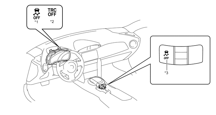
Text in Illustration *1 VSC OFF Indicator Light *2 TRC OFF Indicator Light *3 VSC OFF Switch (Pattern Select Switch Assembly) - - -
The VSC OFF switch (pattern select switch assembly) can select 3 modes (Normal mode, TRC OFF mode, and VSC OFF mode).
-
Briefly pressing the VSC OFF switch (pattern select switch assembly) in Normal mode selects TRC OFF mode.
-
Pressing and holding the VSC OFF switch (pattern select switch assembly) for 3 seconds or more will disable the VSC and TRC functions.
-
Briefly pressing the VSC OFF switch (pattern select switch assembly) in TRC OFF mode or VSC OFF mode or turning the ignition switch off returns to the Normal mode.
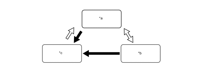
Text in Illustration *a Normal Mode *b TRC OFF Mode *c VSC OFF Mode and TRC OFF Mode - - VSC OFF Switch (Pattern Select Switch Assembly) Operation (Press and Hold for 3 Seconds or More) VSC OFF Switch (Pattern Select Switch Assembly) Operation (Brief) -
The operations of the brake control functions in each mode are as follows:
Mode Brake Control Function Combination Meter Assembly TRC VSC Slip Indicator Light TRC OFF Indicator Light VSC OFF Indicator Light Normal Mode Controllable Controllable Blinks*1
- - TRC OFF Mode Not Controllable Controllable Blinks*2
Illuminates - VSC/TRC OFF Mode Not Controllable Not Controllable*3
Blinks*3
Illuminates Illuminates Tech Tips
*1: When VSC/TRC is active
*2: When VSC is active
*3: If there is a major variance between the left and right driving wheels, the brakes might be applied (A/T Models).
-
-
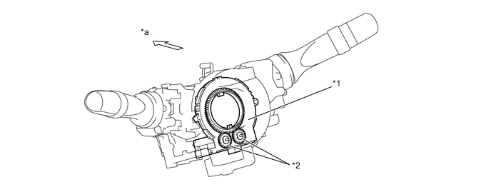
TRACK Switch (Pattern Select Switch Assembly)
-
Use this TRACK switch (pattern select switch assembly) to allow the skid control ECU to switch VSC control between Normal Mode and TRACK Mode.
-
Press the TRACK switch (pattern select switch assembly) to switch VSC to TRACK Mode. When this happens, the driver will be informed that the vehicle is in TRACK Mode by the illumination of the TRACK indicator light and VSC OFF indicator light in the combination meter assembly.
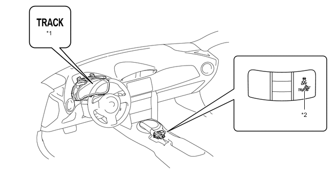
Text in Illustration *1 TRACK Indicator Light *2 TRACK Switch (Pattern Select Switch Assembly) 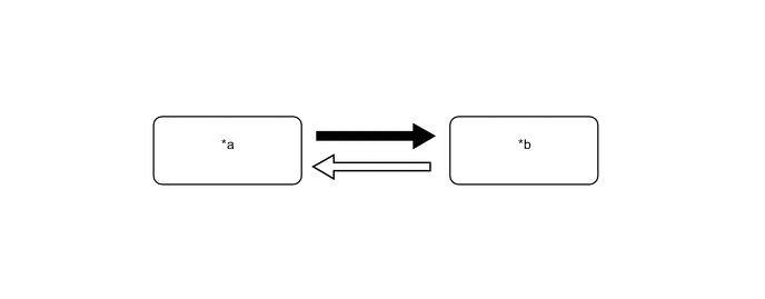
Text in Illustration *a Normal Mode *b TRACK Mode TRACK Switch (Pattern Select Switch Assembly) Operation (Press and Hold for 1 Second or More) TRACK Switch (Pattern Select Switch Assembly) Operation (Brief) 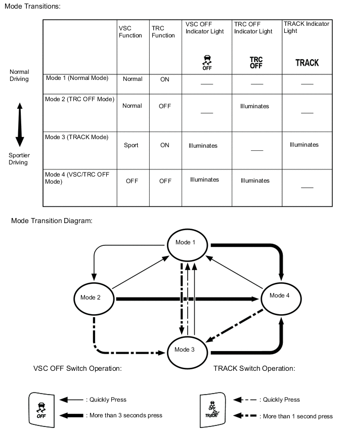
-
-
-
CONSTRUCTION
-
Steering Sensor
-
The steering sensor detects the steering direction and angle, and sends this information to the skid control ECU.
Text in Illustration *1 Steering Sensor *2 Detection Gear *a Front - -
-
-
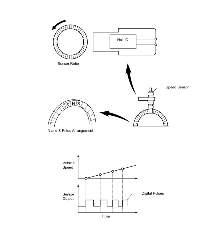
Speed Sensor
-
An active type speed sensor is used. This sensor contains a Hall IC.
-
The sensor rotor, which consists of N and S poles that are arranged in a circle, is integrated with the hub bearing inner race.
-
An active type speed sensor uses a Hall IC to detect magnetic field changes caused when the sensor rotor rotates, and the sensor outputs the detected information to the skid control ECU as digital pulses.
-
To detect the vehicle speed, the frequency of the output pulses is used. Because the active sensor outputs vehicle speed pulses, the speed of the vehicle can be detected at speeds of 1.35 km/h (0.84 mph) or higher.
-
-
Brake Actuator Assembly
-
The brake actuator assembly consists of the brake actuator portion and skid control ECU.
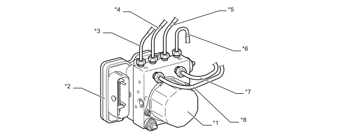
Text in Illustration *1 Brake Actuator Portion *2 Skid Control ECU *3 Right Rear Brake Pipe *4 Left Front Brake Pipe *5 Right Front Brake Pipe *6 Left Rear Brake Pipe *7 Master Cylinder Pipe (Primary Side) *8 Master Cylinder Pipe (Secondary Side) -
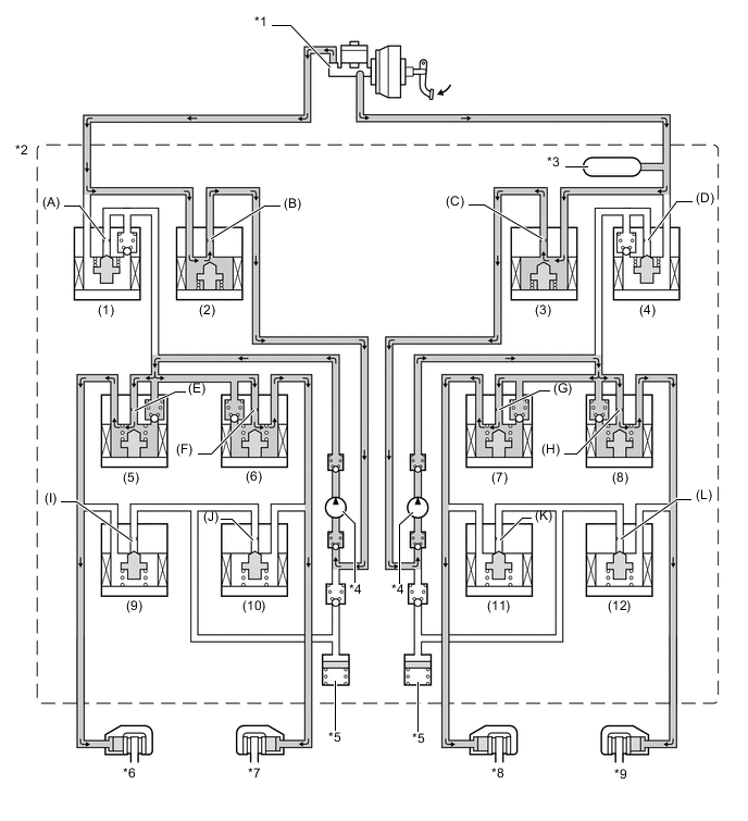
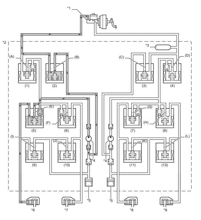
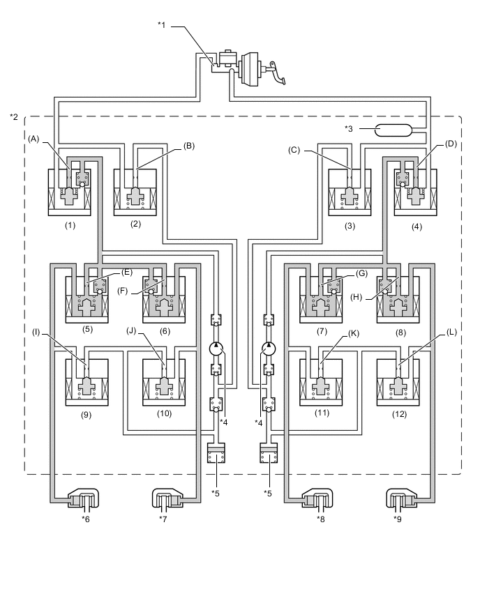
The actuator portion consists of 2 master cylinder cut solenoid valves, 2 reservoir cut solenoid valves, 4 pressure holding solenoid valves, 4 pressure reduction solenoid valves, 2 pumps, 2 reservoirs, and a master cylinder pressure sensor.
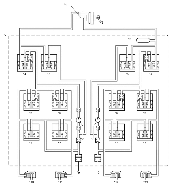
Text in Illustration *1 Brake Master Cylinder Sub-assembly *2 Brake Actuator Assembly *3 Master Cylinder Pressure Sensor *4 Master Cylinder Cut Solenoid Valve *5 Reservoir Cut Solenoid Valve *6 Pressure Holding Solenoid Valve *7 Pressure Reduction Solenoid Valve *8 Pump *9 Reservoir *10 Rear Brake Caliper (Right Side) *11 Front Brake Caliper (Left Side) *12 Front Brake Caliper (Right Side) *13 Rear Brake Caliper (Left Side) - -
-
-
-
OPERATION
-
ABS and EBD
-
Based on the signals received from the 4 speed sensors, the skid control ECU calculates the speed of each wheel, and checks the wheel slipping conditions. In accordance with the slipping condition, the skid control ECU controls each solenoid valve in the brake actuator in order to adjust the fluid pressure of each wheel cylinder in the following 3 modes: pressure increase, pressure holding, and pressure reduction modes.
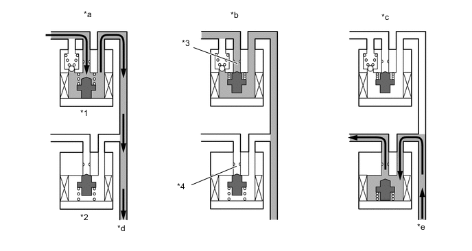
Text in Illustration *1 Pressure Holding Solenoid Valve *2 Pressure Reduction Solenoid Valve *3 Port A *4 Port B *a Pressure Increase Mode *b Pressure Holding Mode *c Pressure Reduction Mode *d to Wheel Cylinder *e from Wheel Cylinder - - -
Each valve operates as shown below:
Pressure Mode Increase Mode Holding Mode Reduction Mode Pressure Holding Solenoid Valve (Port A) Off (Open) On (Closed) On (Closed) Pressure Reduction Solenoid Valve (Port B) Off (Closed) Off (Closed) On (Open) Wheel Cylinder Pressure Increases Holds Reduces
-
-
Brake Assist
-
In the event of emergency braking, the skid control ECU determines the driver's intention based on the speed of the pressure increase in the master cylinder determined by the master cylinder pressure sensor signal. If the skid control ECU judges the need for additional brake assist, pressure is generated by the pump in the brake actuator and directed to the wheel cylinder to apply a large amount of fluid pressure.
Text in Illustration (Brake Assist Operation:) *1 Brake Master Cylinder Sub-assembly *2 Brake Actuator Assembly *3 Master Cylinder Pressure Sensor *4 Pump *5 Reservoir *6 Rear Brake Caliper (Right Side) *7 Front Brake Caliper (Left Side) *8 Front Brake Caliper (Right Side) *9 Rear Brake Caliper (Left Side) - - -
Each valve operates as shown below:
Item Port Brake Assist Not Activated Brake Assist Activated Master Cylinder Cut Solenoid Valves (1), (4) (A), (D) OFF (Open) ON*
Reservoir Cut Solenoid Valve (2), (3) (B), (C) OFF (Closed) ON (Open) Front Brakes Pressure Holding Solenoid Valves (6), (7) (F), (G) OFF (Open) OFF (Open) Pressure Reduction Solenoid Valves (10), (11) (J), (K) OFF (Closed) OFF (Closed) Rear Brakes Pressure Holding Solenoid Valves (5), (8) (E), (H) OFF (Open) OFF (Open) Pressure Reduction Solenoid Valves (9), (12) (I), (L) OFF (Closed) OFF (Closed) Pump OFF ON Tech Tips
*: The solenoid valve switches the hydraulic pressure between "open" and "closed" in accordance with the operating conditions by adjusting continually.
-
-
TRC
-
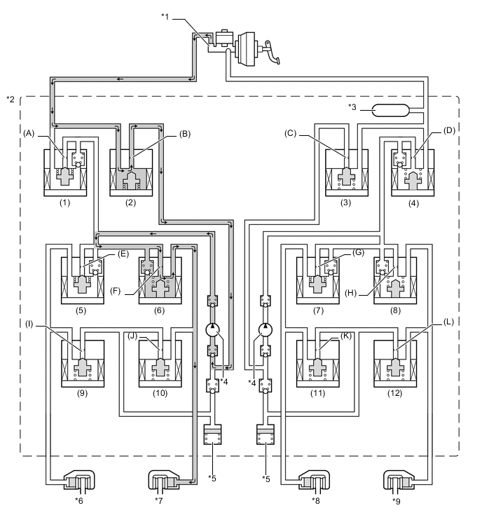
The fluid pressure generated by the pump is regulated by the master cylinder cut solenoid valve to the required pressure. Thus, the wheel cylinders of the drive wheels are controlled in the following 3 modes: pressure increase, pressure holding, and pressure reduction modes to control the slippage of the drive wheels.

Text in Illustration (TRC Operation:) *1 Brake Master Cylinder Sub-assembly *2 Brake Actuator Assembly *3 Master Cylinder Pressure Sensor *4 Pump *5 Reservoir *6 Rear Brake Caliper (Right Side) *7 Front Brake Caliper (Left Side) *8 Front Brake Caliper (Right Side) *9 Rear Brake Caliper (Left Side) - - -
Each valve operates as shown below:
Item Port TRC Not Activated TRC Activated Increase Mode Holding Mode Reduction Mode Master Cylinder Cut Solenoid Valve (1), (4) (A), (D) OFF (Open) ON*
ON*
ON*
Reservoir Cut Solenoid Valve (2), (3) (B), (C) OFF (Closed) ON (Open) ON (Open) ON (Open) Front Brakes Pressure Holding Solenoid Valve (6), (7) (F), (G) OFF (Open) ON (Closed) ON (Closed) ON (Closed) Pressure Reduction Solenoid Valve (10), (11) (J), (K) OFF (Closed) OFF (Closed) OFF (Closed) OFF (Closed) Brake Wheel Cylinder Pressure - - - - - - Rear Brakes Pressure Holding Solenoid Valve (5), (8) (E), (H) OFF (Open) OFF (Open) ON (Closed) ON (Closed) Pressure Reduction Solenoid Valve (9), (12) (I), (L) OFF (Closed) OFF (Closed) OFF (Closed) ON (Open) Brake Wheel Cylinder Pressure - - - Increased Held Reduced Pump OFF ON ON ON Tech Tips
*: The solenoid valve switches the hydraulic pressure between "open" and "closed" in accordance with the operating conditions by adjusting continually.
-
-
VSC
-
The VSC, by way of solenoid valves, controls the fluid pressure generated by the pump and applies it to the brake wheel cylinder of each wheel in the following 3 modes: pressure increase, pressure holding, and pressure reduction modes. As a result, the tendency to front wheel skid or rear wheel skid is controlled.
-
During front wheel skid restraining control, the brake for the right rear wheel on the inside of the turn will be applied. Brakes for all wheels may also be activated if necessary. The diagram below indicates hydraulic pressure pathways in pressure increase mode for controlling front wheel skid when the vehicle makes a right-hand turn. In other modes, the pressure holding valve and pressure reduction valve may be turned on or off as required by ABS and EBD activation patterns.
Text in Illustration (VSC Operation (Front Wheel Skid Restraining):) *1 Brake Master Cylinder Sub-assembly *2 Brake Actuator Assembly *3 Master Cylinder Pressure Sensor *4 Pump *5 Reservoir *6 Rear Brake Caliper (Right Side) *7 Front Brake Caliper (Left Side) *8 Front Brake Caliper (Right Side) *9 Rear Brake Caliper (Left Side) - - -
Each valve operates as shown below:
Item Port VSC Not Activated VSC Activated Increase Mode Holding Mode Reduction Mode Master Cylinder Cut Solenoid Valve (1) (A) OFF (Open) ON*
ON (Closed) ON*
(4) (D) OFF (Open) OFF (Open) OFF (Open) OFF (Open) Reservoir Cut Solenoid Valve (2) (B) OFF (Closed) ON (Open) ON (Open) ON (Open) (3) (C) OFF (Closed) OFF (Closed) OFF (Closed) OFF (Closed) Front Brakes Pressure Holding Solenoid Valve (6) (F) OFF (Open) ON (Closed) ON (Closed) ON (Closed) (7) (G) OFF (Open) ON (Closed) ON (Closed) ON (Closed) Pressure Reduction Solenoid Valve (10) (J) OFF (Closed) OFF (Closed) OFF (Closed) OFF (Closed) (11) (K) OFF (Closed) OFF (Closed) OFF (Closed) OFF (Closed) Brake Wheel Cylinder Pressure Right - - - Increased Held Reduced Left - - - - - - Rear Brakes Pressure Holding Solenoid Valve (5) (E) OFF (Open) OFF (Open) ON (Closed) ON (Closed) (8) (H) OFF (Open) ON (Closed) ON (Closed) ON (Closed) Pressure Reduction Solenoid Valve (9) (I) OFF (Closed) OFF (Closed) OFF (Closed) ON (Open) (12) (L) OFF (Closed) OFF (Closed) OFF (Closed) OFF (Closed) Brake Wheel Cylinder Pressure Right - - - Increased Held Reduced Left - - - - - - Pump OFF ON ON ON Tech Tips
*: The solenoid valve switches the hydraulic pressure between "open" and "closed" in accordance with the operating conditions by adjusting continually.
-
During rear wheel skid restraining control, the brake for the front wheel on the outside of the turn will be applied. The diagram below indicates hydraulic pressure pathways in pressure increase mode for controlling rear wheel skid when the vehicle makes a right-hand turn. In other modes, the pressure holding valve and pressure reduction valve may be turned on or off as required by ABS and EBD activation patterns.
Text in Illustration (VSC Operation (Rear Wheel Skid Restraining):) *1 Brake Master Cylinder Sub-assembly *2 Brake Actuator Assembly *3 Master Cylinder Pressure Sensor *4 Pump *5 Reservoir *6 Rear Brake Caliper (Right Side) *7 Front Brake Caliper (Left Side) *8 Front Brake Caliper (Right Side) *9 Rear Brake Caliper (Left Side) - - -
Each valve operates as shown below:
Item Port VSC Not Activated VSC Activated Increase Mode Holding Mode Reduction Mode Master Cylinder Cut Solenoid Valve (1), (4) (A), (D) OFF (Open) ON*
ON (Closed) ON*
Reservoir Cut Solenoid Valve (2), (3) (B), (C) OFF (Closed) ON (Open) ON (Open) ON (Open) Front Brakes Pressure Holding Solenoid Valve (6) (F) OFF (Open) OFF (Open) ON (Closed) ON (Closed) (7) (G) OFF (Open) ON (Closed) ON (Closed) ON (Closed) Pressure Reduction Solenoid Valve (10) (J) OFF (Closed) OFF (Closed) OFF (Closed) ON (Open) (11) (K) OFF (Closed) OFF (Closed) OFF (Closed) OFF (Closed) Brake Wheel Cylinder Pressure Right - - - - - - Left - - - Increased Held Reduced Rear Brakes Pressure Holding Solenoid Valve (5) (E) OFF (Open) ON (Closed) ON (Closed) ON (Closed) (8) (H) OFF (Open) ON (Closed) ON (Closed) ON (Closed) Pressure Reduction Solenoid Valve (9) (I) OFF (Closed) OFF (Closed) OFF (Closed) OFF (Closed) (12) (L) OFF (Closed) OFF (Closed) OFF (Closed) OFF (Closed) Brake Wheel Cylinder Pressure Right - - - - - - Left - - - - - - Pump OFF ON ON ON Tech Tips
*: The solenoid valve switches the hydraulic pressure between "open" and "closed" in accordance with the operating conditions by adjusting continually.
-
-
Hill-start Assist Control
-
Hill-start Assist Control controls the brakes*by maintaining the master cylinder fluid pressure produced by depressing the brake pedal.
Tech Tips
*: Approximately 2 seconds at the maximum.
-
During Hill-start Assist Control, the hill-start assist indicator light blinks.
Text in Illustration (Hill-start Assist Control Operation:) *1 Brake Master Cylinder Sub-assembly *2 Brake Actuator Assembly *3 Master Cylinder Pressure Sensor *4 Pump *5 Reservoir *6 Rear Brake Caliper (Right Side) *7 Front Brake Caliper (Left Side) *8 Front Brake Caliper (Right Side) *9 Rear Brake Caliper (Left Side) - - -
Each valve operates as shown below:
Item Port Hill-start Assist Control Operation Not Activated Pressure Holding Mode Pressure Reduction Mode Master Cylinder Cut Solenoid Valve (1), (4) (A), (D) OFF (Open) ON*
ON*
Reservoir Cut Solenoid Valve (2), (3) (B), (C) OFF (Closed) OFF (Closed) OFF (Closed) Front Brake Pressure Holding Solenoid Valve (6) (F) OFF (Open) OFF (Open) OFF (Open) (7) (G) OFF (Open) OFF (Open) OFF (Open) Pressure Reduction Solenoid Valve (10) (J) OFF (Closed) OFF (Closed) OFF (Closed) (11) (K) OFF (Closed) OFF (Closed) OFF (Closed) Wheel Cylinder Pressure Right - - - Holds Reduces Left - - - Holds Reduces Rear Brake Pressure Holding Solenoid Valve (5) (E) OFF (Open) OFF (Open) OFF (Open) (8) (H) OFF (Open) OFF (Open) OFF (Open) Pressure Reduction Solenoid Valve (9) (I) OFF (Closed) OFF (Closed) OFF (Closed) (12) (L) OFF (Closed) OFF (Closed) OFF (Closed) Wheel Cylinder Pressure Right - - - Holds Reduces Left - - - Holds Reduces Pump OFF ON ON Tech Tips
*: The solenoid valve switches the hydraulic pressure between "open" and "closed" in accordance with the operating conditions by adjusting continually.
-
-
-
FAIL-SAFE
-
If a failure occurs in the skid control ECU, sensors, or brake actuator assembly, the system continues performing brake control by excluding the failed area and using only the areas that are operating normally.
-
-
DIAGNOSIS
-
If the skid control ECU detects a malfunction in the brake control system, the warning lights or indicator light illuminate. At the same time, a Diagnostic Trouble Code (DTC) is stored in the memory of the skid control ECU.
-
This system has a sensor signal check (test mode) function.
-
For details of DTCs and the check function, refer to the Repair Manual.
-