BLIND SPOT MONITOR SYSTEM, Diagnostic DTC:C1AB2
| DTC Code | DTC Name |
|---|---|
| C1AB2 | Short to GND in Outer Mirror Indicator(Master) |
DESCRIPTION
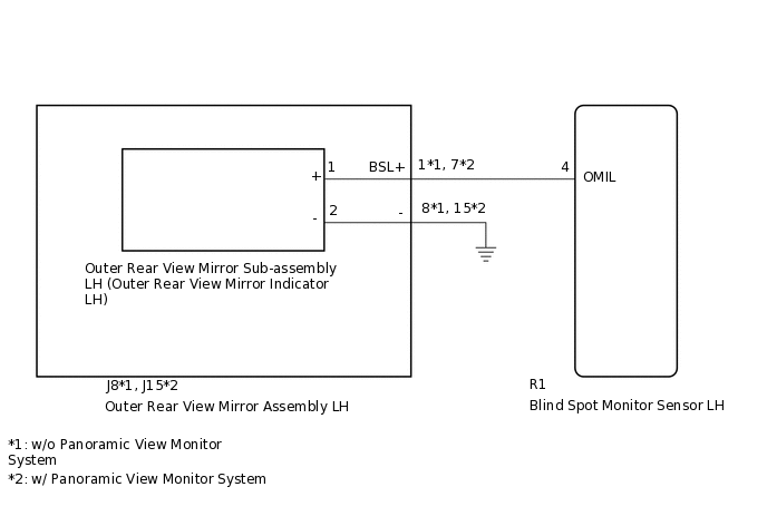
This DTC is stored when the blind spot monitor sensor LH detects a ground short in the outer rear view mirror indicator LH.
DTC No. |
Detection Item |
DTC Detection Condition |
Trouble Area |
|---|---|---|---|
C1AB2 |
Short to GND in Outer Mirror Indicator(Master) |
|
|
WIRING DIAGRAM
CAUTION / NOTICE / HINT
When checking for DTCs, make sure that the blind spot monitor system is on.
PROCEDURE
CHECK DTC
Clear the DTCs.
Body Electrical > Blind Spot Monitor Master > Clear DTCs
Recheck for DTCs and check if the same DTC is output again.
Body Electrical > Blind Spot Monitor Master > Trouble Codes
Result
Result
Proceed to
No DTCs are output
A
DTCs are output
B
CHECK HARNESS AND CONNECTOR (OUTER REAR VIEW MIRROR INDICATOR LH CIRCUIT)
Disconnect the R1 blind spot monitor sensor LH connector.
Disconnect the J8*1 or J15*2 outer rear view mirror assembly LH connector.
*1: w/o Panoramic View Monitor System
*2: w/ Panoramic View Monitor System
Measure the resistance according to the value(s) in the table below.
Standard Resistance
Tester Connection
Condition
Specified Condition
J8-1 (BSL+) - Body ground
Always
10 kΩ or higher
Result
Proceed to
OK
NG
NG REPAIR OR REPLACE HARNESS OR CONNECTOR
INSPECT OUTER REAR VIEW MIRROR SUB-ASSEMBLY LH
Remove the outer rear view mirror sub-assembly LH.
Inspect the outer rear view mirror sub-assembly LH.
Result
Proceed to
OK
NG
REPLACE OUTER REAR VIEW MIRROR ASSEMBLY LH
Replace the outer rear view mirror assembly LH.
Clear the DTCs.
Body Electrical > Blind Spot Monitor Master > Clear DTCs
Recheck for DTCs and check if the same DTC is output again.
Body Electrical > Blind Spot Monitor Master > Trouble Codes
Result
Result
Proceed to
No DTCs are output
A
DTCs are output
B
A END (OUTER REAR VIEW MIRROR ASSEMBLY LH IS DEFECTIVE)