ENGINE IMMOBILISER SYSTEM, Diagnostic DTC:B2797
| DTC Code | DTC Name |
|---|---|
| B2797 | Communication Malfunction No. 1 |
DESCRIPTION
This DTC is stored when a communication error occurs between the transponder key amplifier and transponder key ECU assembly. Some possible reasons for the communication error are: 1) 2 or more ignition keys are positioned too close together, or 2) noise is occurring in the communication line.
| DTC Code | DTC Detection Condition | Trouble Area | DTC Output Confirmation Operation |
|---|---|---|---|
| B2797 | A key with a BCC malfunction is inserted into the ignition key cylinder (1 trip detection logic*). |
|
Insert the key into the ignition key cylinder |
-
*: Only output while a malfunction is present.
| Vehicle Condition when Malfunction Detected | Fail-safe Operation when Malfunction Detected |
|---|---|
| Engine cannot be started. | - |
| DTC Code | Data List and Active Test |
|---|---|
| B2797 | BCC Malfunction |
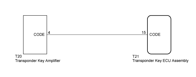
WIRING DIAGRAM
INSPECTION PROCEDURE
Note
-
When replacing the transponder key ECU assembly, refer to the Service Bulletin.
-
After performing repairs, perform the operation that fulfills the DTC output confirmation operation, and then confirm that no DTCs are output again.
PROCEDURE
-
CHECK KEY
-
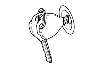
Check whether the ignition key being used is near other ignition keys, as shown in the illustration. Also, check whether a key ring is in contact with the key grip.
Result Result Proceed to Key is near other keys and/or key ring is in contact with key grip A Key is not near other keys and/or key ring is not in contact with key grip B
B 
CHECK HARNESS AND CONNECTOR (TRANSPONDER KEY ECU - TRANSPONDER KEY AMPLIFIER) Click here
A 
-
-
CHECK FOR DTC
-
Separate the keys from each other and/or remove the key ring.
-
Clear the DTC Click here.
-
Insert a key into the ignition key cylinder, and then remove it. Repeat this for all the other keys.
-
Check that no code is output.
OK DTC B2797 is not output.
NG
CHECK HARNESS AND CONNECTOR (TRANSPONDER KEY ECU - TRANSPONDER KEY AMPLIFIER) Click here
OK 
END
-
-
CHECK HARNESS AND CONNECTOR (TRANSPONDER KEY ECU - TRANSPONDER KEY AMPLIFIER)
-
Disconnect the T21 transponder key ECU assembly connector.
-
Disconnect the T20 transponder key amplifier connector.
-
Measure the resistance according to the value(s) in the table below.
Standard Resistance Tester Connection Condition Specified Condition T21-15 (CODE) - T20-4 (CODE) Always Below 1 Ω
NG 
REPAIR OR REPLACE HARNESS OR CONNECTOR
OK
-
-
CHECK TRANSPONDER KEY ECU ASSEMBLY
-
Using an oscilloscope or the intelligent tester, check for noise in the waveform between the terminals of the T20 transponder key amplifier connector and T21 transponder key ECU assembly connector.
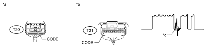
Text in Illustration *a Component with harness connected
(Transponder Key Amplifier)
*b Component with harness connected
(Transponder Key ECU Assembly)
*c Noise should not appear - - Measurement Condition Item Content Tester Connection T21-15 (CODE) - T20-4 (CODE) Tool Setting 5 V/DIV., 20 msec./DIV. Condition Key inserted in ignition key cylinder OK No noise is present (see illustration).
NG
FIND CAUSE OF NOISE AND REMOVE IT
OK
-
-
REPLACE TRANSPONDER KEY AMPLIFIER (OPERATION)
-
Temporally replace the transponder key amplifier with a new or normally functioning one Click here.
NEXT
-
-
CHECK WHETHER ENGINE STARTS
-
Check that the engine starts normally.
OK Engine starts.
NG
REPLACE TRANSPONDER KEY ECU ASSEMBLY
OK
END (TRANSPONDER KEY AMPLIFIER IS DEFECTIVE)
-