FUEL INJECTOR INSTALLATION
CAUTION / NOTICE / HINT
When replacing the injector assemblies (including exchanging the injector assemblies between the cylinders), it is necessary to replace the injection pipe sub-assemblies with new ones.
After replacing any of the injector assemblies, perform both the "Injector Compensation" and the "Pilot Quantity Learning Values Reset" functions using the GTS.
PROCEDURE
INSTALL INJECTOR ASSEMBLY
Note:Before installing the injector assembly, check for carbon, foreign matter, etc. on the sealing surfaces of the cylinder head and injector assembly. Clean them if necessary.
Install 4 new injection nozzle seats to the cylinder head.
-
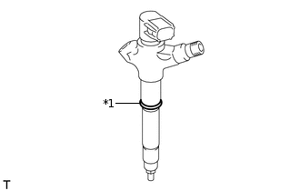
*1
O-ring
Install new O-rings to each injector assembly.
Apply a light coat of engine oil to the O-rings on each injector assembly.
Install the 4 injector assemblies to the cylinder head.
Note:Fit the injector assemblies to the injection nozzle seats.
INSTALL NO. 1 NOZZLE HOLDER CLAMP
-
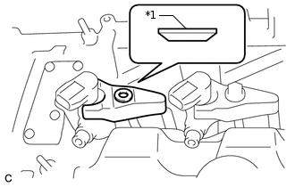
*1
Washer
Install the No. 1 nozzle holder clamps and washers as shown in the illustration.
Note:Be careful of the mounting orientation (beveled edge) of the washer.
Temporarily install the nozzle holder clamp bolts.
Note:When temporarily installing the nozzle holder clamps and No. 1 nozzle holder clamp bolts, be careful not to position them at an angle.
Tip:Apply a light coat of engine oil to the threads of the nozzle holder clamp bolts.
-
Temporarily install the No. 1 nozzle leakage pipe with 4 new gaskets, the 4 union bolts and bolt.
-
Temporarily install the injection pipe sub-assembly.
Tighten the 4 nozzle holder clamp bolts.
25 N*m
255 kgf*cm
18 ft.*lbf
-
INSTALL NO. 1 NOZZLE LEAKAGE PIPE
Tighten the 4 union bolts.
18 N*m
184 kgf*cm
13 ft.*lbf
Tighten the bolt.
20.5 N*m
209 kgf*cm
15 ft.*lbf
INSTALL INJECTION PIPE SUB-ASSEMBLY
-
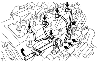
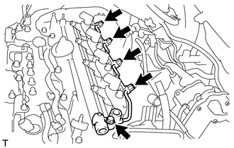
Using a 14 mm union nut wrench, tighten the 4 nuts at the common rail assembly end of the injection pipe sub-assemblies.
30 N*m
306 kgf*cm
22 ft.*lbf
Note:Use the torque value compensation formula to calculate the torque value for use when a torque wrench is combined with a tool such as a union nut wrench.
Using a 14 mm union nut wrench, tighten the 4 nuts at the injector assembly end of the injection pipe sub-assemblies.
30 N*m
306 kgf*cm
22 ft.*lbf
Note:Use the torque value compensation formula to calculate the torque value for use when a torque wrench is combined with a tool such as a union nut wrench.
Install the 4 injection pipe clamps with the 2 bolts.
5.0 N*m
51 kgf*cm
44 in.*lbf
-
INSTALL NO. 2 NOZZLE LEAKAGE PIPE
-
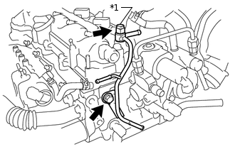
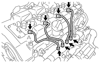
*1
Check Valve
Temporarily install the No. 2 nozzle leakage pipe with a new gasket, the check valve and bolt.
Tighten the check valve.
31.5 N*m
321 kgf*cm
23 ft.*lbf
Tighten the bolt.
31.5 N*m
321 kgf*cm
23 ft.*lbf
-
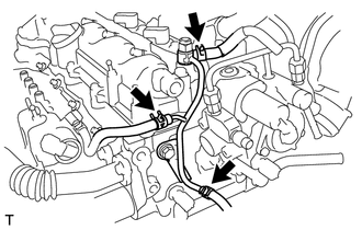
Connect the 3 fuel hoses with the 3 clips.
-
INSTALL FUEL TUBE SUB-ASSEMBLY
INSTALL FUEL HOSE PROTECTOR
CONNECT ENGINE WIRE
Connect the engine wire with the bolt and 5 nuts.
8.0 N*m
82 kgf*cm
71 in.*lbf
Install the 2 wire harness brackets with the 2 bolts.
12.5 N*m
127 kgf*cm
9 ft.*lbf
Engage the 2 wire harness clamps.
Connect the glow plug connector.
Connect the connector to the pressure control valve.
Connect the connector to the fuel pressure sensor.
-
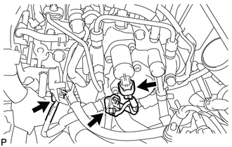
Connect the 3 connectors.
Connect the 4 connectors to the 4 injector assemblies.
INSTALL AIR CLEANER CASE SUB-ASSEMBLY
INSTALL AIR CLEANER CAP SUB-ASSEMBLY
CONNECT CABLE TO NEGATIVE BATTERY TERMINAL
Note:When disconnecting the cable, some systems need to be initialized after the cable is reconnected.
PERFORM REGISTRATION AND INITIALIZATION
Perform registration of injector assembly compensation codes.
Perform registration of pilot quantity learning.
BLEED AIR FROM FUEL SYSTEM
INSPECT FOR FUEL LEAK
INSTALL NO. 1 ENGINE COVER
INSTALL OUTER COWL TOP PANEL
INSTALL DIFFERENTIAL PRESSURE SENSOR ASSEMBLY
INSTALL NO. 2 HEATER AIR DUCT SPLASH SHIELD SEAL
INSTALL WATER GUARD PLATE LH
INSTALL WINDSHIELD WIPER MOTOR AND LINK ASSEMBLY