CRUISE CONTROL SYSTEM TC and CG Terminal Circuit
| DTC Code | DTC Name |
|---|---|
| TC and CG Terminal Circuit |
DESCRIPTION
Connecting terminals TC and CG of the DLC3 causes the system to enter self-diagnostic mode.
When a particular warning light remains blinking, a ground short in the wiring of terminal TC of the DLC3 or an internal ground short in the relevant ECU is suspected.
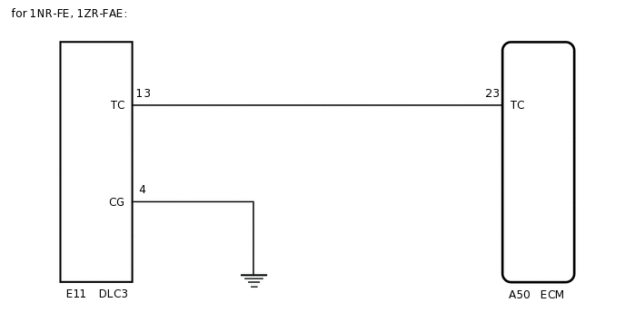
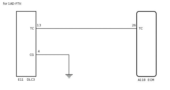
WIRING DIAGRAM
PROCEDURE
CHECK HARNESS AND CONNECTOR (TERMINAL TC of DLC3 - ECM)
Disconnect the ECM connector.
Measure the resistance according to the value(s) in the table below.
Standard Resistance (Check for Open)
Table 1. for 1NR-FE, 1ZR-FAE Tester Connection
Condition
Specified Condition
A50-23 (TC) - E11-13 (TC)
Always
Below 1 Ω
Table 2. for 1AD-FTV Tester Connection
Condition
Specified Condition
A118-26 (TC) - E11-13 (TC)
Always
Below 1 Ω
Result
Proceed to
OK
NG
NG REPAIR OR REPLACE HARNESS OR CONNECTOR (DLC3 - ECM)
CHECK HARNESS AND CONNECTOR (TERMINAL CG of DLC3 - BODY GROUND)
-
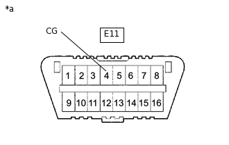
*a
DLC3
Measure the resistance according to the value(s) in the table below.
Standard Resistance (Check for Open)
Tester Connection
Condition
Specified Condition
E11-4 (CG) - Body ground
Always
Below 1 Ω
Result
Proceed to
OK
NG
NG REPAIR OR REPLACE HARNESS OR CONNECTOR (DLC3 - BODY GROUND)
-
CHECK HARNESS AND CONNECTOR (TERMINAL TC of DLC3 - BODY GROUND)
-
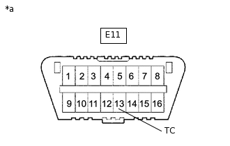
*a
DLC3
Measure the resistance according to the value(s) in the table below.
Standard Resistance (Check for Open)
Tester Connection
Condition
Specified Condition
E11-13 (TC) - Body ground
Always
10 kΩ or higher
Result
Proceed to
OK
NG
NG REPAIR OR REPLACE HARNESS OR CONNECTOR OR EACH ECU
-