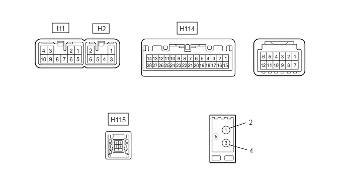
AUDIO AND VISUAL SYSTEM(for Radio Receiver Type) TERMINALS OF ECU
CHECK RADIO RECEIVER ASSEMBLY
Terminal No. (Symbol)
Wiring Color
Terminal Description
Condition
Specified Condition
H1-1 (FR+) - H1-7 (GND1)
LG - BR
Sound signal (Front right)
Audio system playing
Waveform synchronized with sound is output
H1-2 (FL+) - H1-7 (GND1)
P - BR
Sound signal (Front left)
Audio system playing
Waveform synchronized with sound is output
H1-3 (ACC1) - H1-7 (GND1)
GR - BR
Power source (ACC)
Ignition switch off
Below 1 V
Ignition switch ACC
11 to 14 V
H1-4 (+B1) - H1-7 (GND1)
SB - BR
Power source (+B)
Always
11 to 14 V
H1-5 (FR-) - H1-7 (GND1)
L - BR
Sound signal (Front right)
Audio system playing
Waveform synchronized with sound is output
H1-6 (FL-) - H1-7 (GND1)
V - BR
Sound signal (Front left)
Audio system playing
Waveform synchronized with sound is output
H1-7 (GND1) - Body ground
BR - Body ground
Ground
Always
Below 1 Ω
H1-10 (ILL+) - H1-7 (GND1)
G - BR
Illumination signal
Light control switch off → tail or head
Below 1 V → 11 to 14 V
H2-1 (RR+) - H1-7 (GND1)
R - BR
Sound signal (Rear right)
Audio system playing
Waveform synchronized with sound is output
H2-2 (RL+) - H1-7 (GND1)
Y - BR
Sound signal (Rear left)
Audio system playing
Waveform synchronized with sound is output
H2-3 (RR-) - H1-7 (GND1)
W - BR
Sound signal (Rear right)
Audio system playing
Waveform synchronized with sound is output
H2-6 (RL-) - H1-7 (GND1)
B - BR
Sound signal (Rear left)
Audio system playing
Waveform synchronized with sound is output
H114-17 (SPD) - H1-7 (GND1)
V - BR
Vehicle speed signal
Drive wheels turned slowly
Pulse generation
H114-11 (AGND) - Body ground
Shielded - Body ground
Shield ground
Always
Below 1 Ω
H114-21 (SW1) - H1-7 (GND1)
W - BR
Steering pad switch signal
Steering pad switch not operated
2.97 to 3.56 V
SEEK+ switch pushed
0.27 to 0.35 V
SEEK- switch pushed
0.86 to 1.03 V
VOL+ switch pushed
1.51 to 1.79 V
VOL- switch pushed
2.22 to 2.66 V
H114-22 (SW2) - H1-7 (GND1)
R - BR
Steering pad switch signal
Steering pad switch not operated
2.97 to 3.56 V
MODE switch pushed
0.27 to 0.35 V
On hook switch pushed
0.86 to 1.03 V
Off hook switch pushed
1.51 to 1.79 V
Voice switch pushed
2.22 to 2.66 V
H114-23 (SWG) - Body ground
W-B - Body ground
Ground
Always
Below 1 Ω
H114-25 (ADPG) - H1-7 (GND1)
L - BR
External device connection detection signal
External device connected
Below 1 V
H114-26 (VAR+) - H1-7 (GND1)
W - BR
Sound signal (Right)
External device playing (When stereo jack used)
A waveform synchronized with sound is output
H114-27 (VA-) - H1-7 (GND1)
R - BR
Ground
Always
Below 1 Ω
H114-28 (VAL+) - H1-7 (GND1)
B - BR
Sound signal (Left)
External device playing (When stereo jack used)
A waveform synchronized with sound is output
H115-1 - H115-4
# - #
Power source
Always
4.5 to 5.5 V
H115-2 - H115-4
# - #
Data signal
USB device or "iPod" connected
-
H115-3 - H115-4
# - #
Data signal
USB device or "iPod" connected
-
H115-4 - Body ground
# - Body ground
Ground
Always
Below 1 Ω
H115-5 - Body ground
Shielded - Body ground
Shield ground
Always
Below 1 Ω
#: There is no wire color information.