CRUISE CONTROL SYSTEM(for 1WW) TERMINALS OF ECU
CHECK ECM
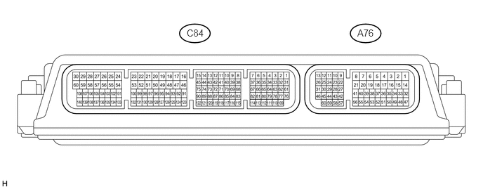
Disconnect the A76 ECM connector.
Note:After turning the ignition switch off, make sure to wait at least 6 minutes before disconnecting the ECM connector or replacing the ECM.
Measure the voltage and resistance according to the value(s) in the table below.
Terminal No. (Symbol)
Wiring Color
Terminal Description
Condition
Specified Condition
A76-15 (BATT) - Body ground
B - Body ground
Power source circuit
Always
11 to 14 V
A76-37 (IGSW) - Body ground
B - Body ground
IG power source circuit
Ignition switch ON
11 to 14 V
Ignition switch off
Below 1 V
A76-10 (ST1-) - Body ground
R-W - Body ground
Stop light switch signal circuit
Ignition switch ON, brake pedal released
11 to 14 V
Ignition switch ON, brake pedal depressed
Below 1 V
A76-48 (STP) - Body ground
V - Body ground
Stop light switch signal circuit
Brake pedal depressed
11 to 14 V
Brake pedal released
Below 1 V
A76-7 (D) - Body ground
W - Body ground
Clutch switch signal circuit
Ignition switch ON, clutch pedal depressed
11 to 14 V
Ignition switch ON, clutch pedal released
Below 1 V
A76-41 (CCS) - A76-42 (ECCS)
L - BR
Cruise control switch circuit
Cruise control switch on
Below 2.5 Ω
Cruise control switch off
10 MΩ or higher
+RES switch held on
235 to 245 Ω
-SET switch held on
617 to 643 Ω
CANCEL switch held on
1509 to 1571 Ω
A76-4 (E1) - Body ground
W-B - Body ground
Ground
Always
Below 1 Ω
If the result is not as specified, there may be a malfunction on the wire harness side.