CYLINDER BLOCK(w/ Glow Plug Controller) REPLACEMENT
PROCEDURE
REPLACE STRAIGHT PIN
Remove the 9 straight pins shown in the illustration from the cylinder block sub-assembly.
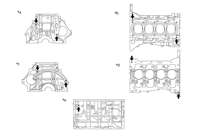
*a
Front Side
*b
Upper Side
*c
Rear Side
*d
Lower Side
*e
LH Side
-
-
Using a plastic hammer, tap in 9 new straight pins.
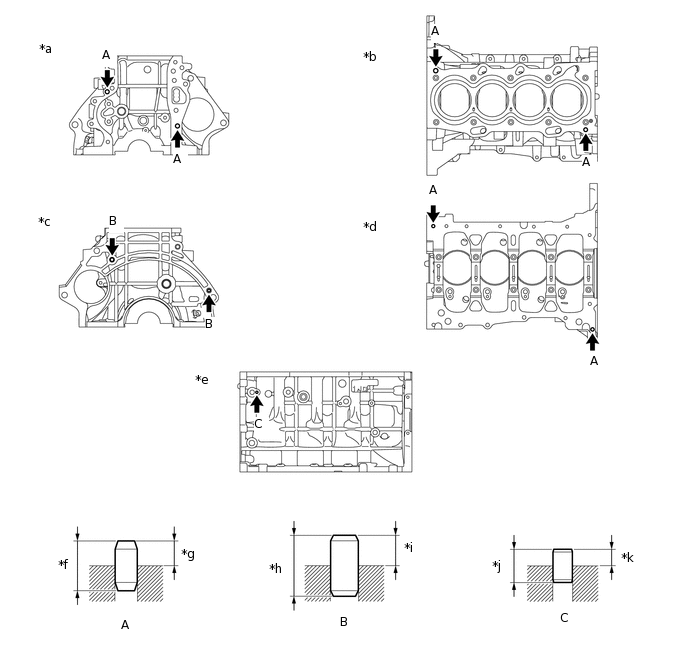
*a
Front Side
*b
Upper Side
*c
Rear Side
*d
Lower Side
*e
LH Side
*f
18.0 mm (0.709 in.)
*g
8.5 to 9.5 mm (0.335 to 0.374 in.)
*h
22.0 mm (0.866 in.)
*i
11.5 to 12.5 mm (0.453 to 0.492 in.)
*j
12.0 mm (0.472 in.)
*k
5.5 to 6.5 mm (0.217 to 0.256 in.)
-
-
REPLACE STUD BOLT
Using an E6 "TORX" socket wrench, remove the 2 stud bolts from the cylinder block sub-assembly.
-
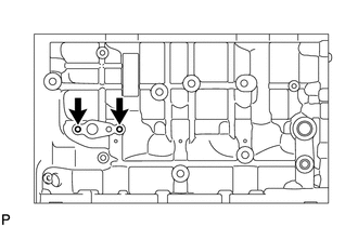
Using an E6 "TORX" socket wrench, install the 2 stud bolts to the cylinder block sub-assembly.
6.0 N*m
61 kgf*cm
53 in.*lbf