SFI SYSTEM, Diagnostic DTC:P0660
| DTC Code | DTC Name |
|---|---|
| P0660 | Intake Manifold Tuning Valve Control Circuit / Open (Bank 1) |
DESCRIPTION
This circuit opens and closes the Intake Air Control Valve (IACV) in response to changes in the engine load in order to increase the intake efficiency (ACIS: Acoustic Control Induction System).
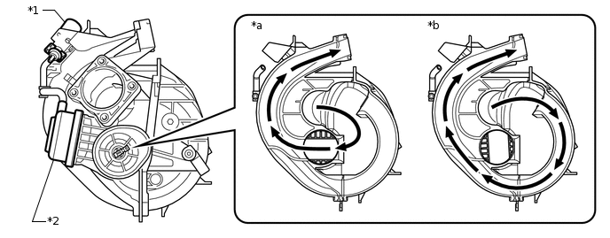
*1 |
Vacuum Switching Valve (for Acoustic Control Induction System) |
*2 |
Intake Air Control Valve |
*a |
Intake Air Control Valve Open |
*b |
Intake Air Control Valve Close |
DTC No. |
Detection Item |
DTC Detection Condition |
Trouble Area |
MIL |
Memory |
|---|---|---|---|---|---|
P0660 |
Intake Manifold Tuning Valve Control Circuit / Open (Bank 1) |
The following conditions are met simultaneously for 0.5 seconds or more (2 trip detection logic):
|
|
Comes on |
DTC stored |
CONFIRMATION DRIVING PATTERN
Connect the GTS to the DLC3.
Turn the ignition switch to ON and turn the GTS on.
Clear the DTCs (even if no DTCs are stored, perform the clear DTC procedure)
Turn the ignition switch off and wait for at least 30 seconds.
Turn the ignition switch to ON and turn the GTS on.
Wait 5 seconds or more.
Enter the following menus: Powertrain / Engine and ECT / Trouble Codes.
Read the pending DTCs.
Tip:If a pending DTC is output, the system is malfunctioning.
If a pending DTC is not output, perform the following procedure.
Enter the following menus: Powertrain / Engine and ECT / Utility / All Readiness.
Input the DTC: P0660.
Check the DTC judgment result.
GTS Display
Description
NORMAL
DTC judgment completed
System normal
ABNORMAL
DTC judgment completed
System abnormal
INCOMPLETE
DTC judgment not completed
Perform driving pattern after confirming DTC enabling conditions
N/A
Unable to perform DTC judgment
Number of DTCs which do not fulfill DTC preconditions has reached ECU memory limit
Tip:If the judgment result shows NORMAL, the system is normal.
If the judgment result shows ABNORMAL, the system has a malfunction.
If the judgment result shows INCOMPLETE or N/A, perform the Confirmation Driving Pattern and check the DTC judgment result again.
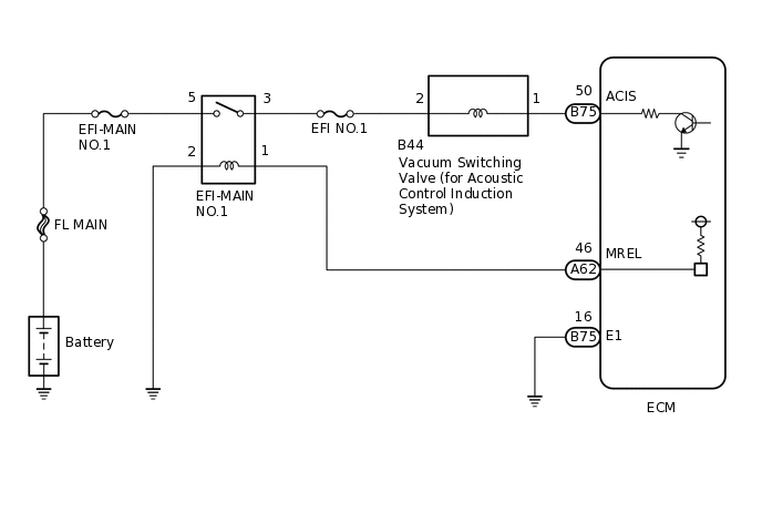
WIRING DIAGRAM
CAUTION / NOTICE / HINT
Inspect the fuses for circuits related to this system before performing the following inspection procedure.
Read freeze frame data using the GTS. The ECM records vehicle and driving condition information as freeze frame data the moment a DTC is stored. When troubleshooting, freeze frame data can help determine if the vehicle was moving or stationary, if the engine was warmed up or not, if the air fuel ratio was lean or rich, and other data from the time the malfunction occurred.
PROCEDURE
PERFORM ACTIVE TEST USING GTS (ACTIVATE THE VSV FOR INTAKE CONTROL)
-
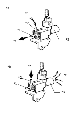
*1
Port F
*2
Port E
*3
Air Filter
*a
Vacuum Switching Valve (for Acoustic Control Induction System) is ON
*b
Vacuum Switching Valve (for Acoustic Control Induction System) is OFF
*c
Air
Disconnect the vacuum hose from port F of the vacuum switching valve (for acoustic control induction system).
Connect the GTS to the DLC3.
Start the engine.
Turn the GTS on.
Enter the following menus: Powertrain / Engine and ECT / Active Test / Activate the VSV for Intake Control.
Powertrain > Engine and ECT > Active Test
Tester Display
Activate the VSV for Intake Control
Operate the vacuum switching valve (for acoustic control induction system).
Check the vacuum switching valve (for acoustic control induction system) air flow when switching the vacuum switching valve (for acoustic control induction system).
OK
Activate the VSV for Intake Control
Specified Condition
ON
Air from port E flows out through port F
OFF
Air from port E flows out through air filter
Result
Proceed to
OK
NG
-
INSPECT VACUUM SWITCHING VALVE (FOR ACOUSTIC CONTROL INDUCTION SYSTEM)
Inspect the vacuum switching valve (for acoustic control induction system) (Click here).
Result
Proceed to
OK
NG
CHECK TERMINAL VOLTAGE (POWER SOURCE OF VACUUM SWITCHING VALVE (FOR ACOUSTIC CONTROL INDUCTION SYSTEM))
-
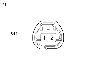
*a
Front view of wire harness connector
(to Vacuum Switching Valve (for Acoustic Control Induction System))
Disconnect the vacuum switching valve (for acoustic control induction system) connector.
Turn the ignition switch to ON.
Measure the voltage according to the value(s) in the table below.
Standard Voltage
Tester Connection
Condition
Specified Condition
B44-2 - Body ground
Ignition switch ON
11 to 14 V
Result
Proceed to
OK
NG
NG REPAIR OR REPLACE HARNESS OR CONNECTOR (VACUUM SWITCHING VALVE (FOR ACOUSTIC CONTROL INDUCTION SYSTEM) - EFI-MAIN NO.1 RELAY)
-
CHECK HARNESS AND CONNECTOR (VACUUM SWITCHING VALVE (FOR ACOUSTIC CONTROL INDUCTION SYSTEM) - ECM)
Disconnect the vacuum switching valve (for acoustic control induction system) connector.
Disconnect the ECM connector.
Measure the resistance according to the value(s) in the table below.
Standard Resistance
Tester Connection
Condition
Specified Condition
B44-1 - B75-50 (ACIS)
Always
Below 1 Ω
B44-1 or B75-50 (ACIS) - Body ground
Always
10 kΩ or higher
Result
Proceed to
OK
NG
NG REPAIR OR REPLACE HARNESS OR CONNECTOR