REAR AXLE SHAFT INSTALLATION
Tech Tips
-
Use the same procedures for the RH side and LH side.
-
The procedures listed below are for the LH side.
-
A bolt without a torque specification is shown in the standard bolt chart Click here.
-
INSTALL REAR AXLE SHAFT BEARING LH
-
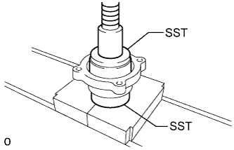
Using SST and a press, press in a new bearing.
- SST
- 09515-21010
- 09950-60020 ( 09951-00810 )
-
-
INSTALL REAR AXLE SHAFT OUTER OIL SEAL
-
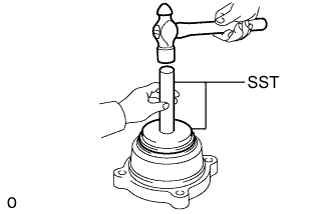
Using SST and a hammer, tap in a new oil seal.
- SST
- 09950-00020 ( 09951-00680 )
- 09950-70010 ( 09951-07150 )
-
-
INSTALL REAR AXLE HUB BOLT LH

-
Install a new gasket and the deflector to the axle shaft.
Tech Tips
Align the 3 oil drain holes.
-
for 2WD:
Pass 5 new hub bolts through the axle hub.
-
for 4WD and Pre-Runner:
Pass 6 new hub bolts through the axle hub.
-
Secure the axle shaft between aluminum plates in a vise.
-
for 2WD:
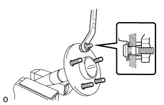
Temporarily install a washer and nut to each of the 5 hub bolts as shown in the illustration.
-
for 4WD and Pre-Runner:
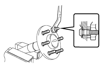
Temporarily install a washer and nut to each of the 6 hub bolts as shown in the illustration.
-
Install the hub bolts by tightening each nut.
-
Remove the washer and nut from each hub bolt.
-
-
INSTALL BACKING PLATE TO REAR AXLE HOUSING SETTING BOLT
-
Position the backing plate on the bearing case.
-
Using 2 socket wrenches and a press, press in 4 new setting bolts.
-
-
INSTALL REAR AXLE BEARING INNER RETAINER LH
-
Heat a new retainer to approximately 70 to 130°C (158 to 266°F).
-
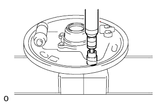
Install a new shaft washer and the retainer to the axle shaft as shown in the illustration.
Note
-
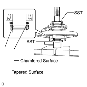
Install the shaft washer with its tapered surface facing downward.
-
Install the retainer with its chamfered surface facing downward.
-
-
Using SST and a press, press in the axle shaft.
- SST
- 09951-01100
- 09631-12090
- 09726-40010
-
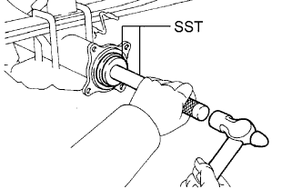
Using a snap ring expander, install a new snap ring.
-
-
INSTALL REAR AXLE BEARING INNER RETAINER LH AND REAR SKID CONTROL ROTOR (w/ ABS, VSC)
-
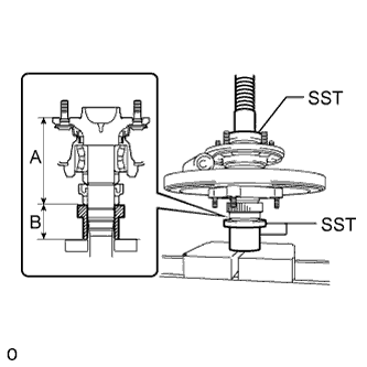
Using SST and a press, press in a new skid control rotor and retainer to the axle shaft until the lengths are within the standard range.
- SST
- 09951-01100
- 09631-12090
- 09726-40010
Standard length Length A Length B 133.2 +/-0.6 mm (5.244 +/-0.0236 in.) 56 mm (2.205 in.) Note
If this installation measurement is not followed precisely, oil leaks and other mechanical failures will result. Follow the assembly instructions closely, and confirm that parts have been installed according to the standard length measurement.
Tech Tips
It may be easier to verify the installation by adding the length of the SST to the standard length, and then measuring the height from the surface of the press.
-
-
INSTALL REAR AXLE SHAFT OIL SEAL LH
-
Using SST and a hammer, tap in a new oil seal.
- SST
- 09950-60020 ( 09951-00770 )
- 09950-70010 ( 09951-07150 )
-
-
INSTALL O-RING
-
Install a new O-ring to the axle housing.
-
-
INSTALL REAR AXLE SHAFT WITH BACKING PLATE
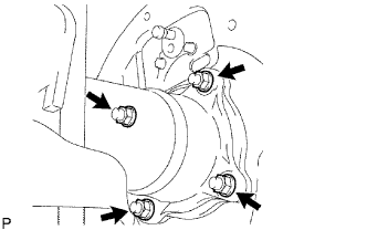
-
Install the axle shaft with backing plate with the 4 nuts.
- Torque:
- 43 N*m { 438 kgf*cm, 32 ft.*lbf }
-
-
CONNECT PARKING BRAKE CABLE
-
Connect the parking brake cable with the 2 bolts.
- Torque:
- 9.0 N*m { 92 kgf*cm, 80 in.*lbf }
-
-
INSTALL REAR BRAKE SHOE (for 2WD)
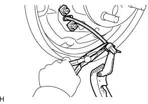
-
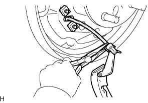
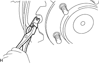
Using needle-nose pliers, connect the No. 3 parking brake cable to the parking brake shoe lever.
-
Using needle-nose pliers, install the adjust lever tension spring to the automatic adjust lever and rear brake shoe.
-
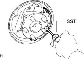
Using SST, install the shoe, pin, shoe hold down spring and shoe hold down spring cup.
- SST
- 09718-00010
-
-
INSTALL FRONT BRAKE SHOE (for 2WD)
-
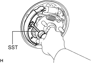
Connect the shoe tension spring to the front brake shoe and rear brake shoe.
-
Using SST, install the shoe, shoe hold down spring and shoe hold down spring cup.
- SST
- 09718-00010
-
-
INSTALL BRAKE SHOES (for 4WD and Pre-Runner)
-
Using needle-nose pliers, connect the No. 3 parking brake cable to the parking brake shoe lever.
-
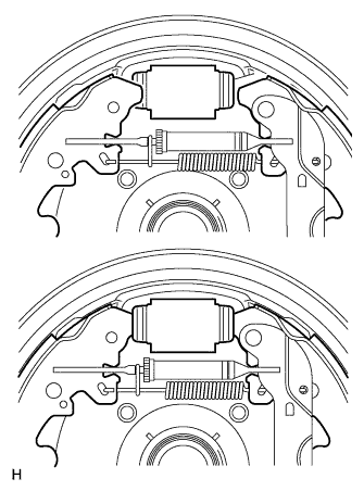
Install the strut set and return spring to the shoe.
-
Attach the support clip to exposed threads of the strut set.
Note
The support clip shall not contact the adjuster nut.
-
Using needle-nose pliers, hook the support clip around the spring.
Note
Be careful not to damage the spring.
-
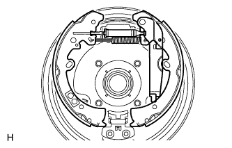
Install the front and rear brake shoes.
-
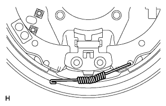
Move one of the shoes upward and install the shoe tension spring.
-
Install the shoe front or rear side to the cylinder. Then install the other side of the shoe to the other side of the cylinder.
Tech Tips
After one side of the shoe is installed to the cylinder, hold that side of the shoe steady. Then widen the opening of the shoe by pulling the other side of the shoe outward and install it to the other side of the cylinder.
Note
Be careful not to damage the cylinder dust boot.
-
Using pliers, install the front brake shoe, rear brake shoe, pins and shoe hold down springs.
-
-
INSTALL REAR SPEED SENSOR LH (w/ ABS, VSC)
-
Install the speed sensor RH with the bolt.
- Torque:
- 8.5 N*m { 87 kgf*cm, 75 in.*lbf }
Note
-
Make sure there are no pieces of iron or other foreign matter attached to the sensor tip.
-
While inserting the speed sensor into the axle housing hole, do not strike or damage the sensor tip.
-
After installing the speed sensor, make sure there is no clearance or foreign matter between the sensor stay part and the axle housing.
-
Install the harness clamp with the bolt.
- Torque:
- 13 N*m { 127 kgf*cm, 9 ft.*lbf }
Note
-
When installing the clamp, do not twist the wire harness.
-
Make sure the clamp rotation stopper touches the installation position.
-
Attach the 2 clamps.
Note
When attaching the clamps, do not twist the wire harness.
-
Attach the connector.
Note
-
Securely attach the connector.
-
When attaching the connector, do not twist the wire harness.
-
-
Connect the connector.
Note
-
Securely connect the connector.
-
When connecting the connector, do not twist the wire harness.
-
-
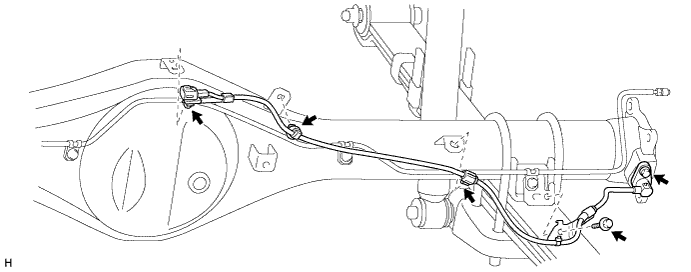
Install the speed sensor LH with the bolt.
- Torque:
- 8.5 N*m { 87 kgf*cm, 75 in.*lbf }
Note
-
Make sure there are no pieces of iron or other foreign matter attached to the sensor tip.
-
While inserting the speed sensor into the axle housing hole, do not strike or damage the sensor tip.
-
After installing the speed sensor, make sure there is no clearance or foreign matter between the sensor stay part and the axle housing.
-
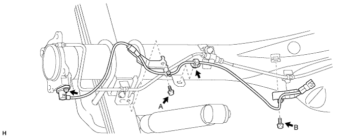
Install the 2 harness clamps with the 2 bolts.
- Torque:
- for bolt A
- 13 N*m { 127 kgf*cm, 9 ft.*lbf }
- for bolt B
- 32 N*m { 326 kgf*cm, 24 ft.*lbf }
Note
-
When installing the clamps, do not twist the wire harness.
-
Make sure the clamp rotation stopper touches the installation position.
-
Attach the clamp.
Note
When attaching the clamp, do not twist the wire harness.
-
-
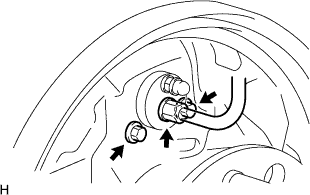
CONNECT BRAKE LINE (for 2WD)
-
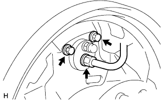
Install the cylinder with the 2 bolts.
- Torque:
- 9.5 N*m { 97 kgf*cm, 84 in.*lbf }
-
Using a union nut wrench, connect the brake line.
- Torque:
- 15 N*m { 155 kgf*cm, 11 ft.*lbf }
Note
Use the formula to calculate special torque values for situations where a union nut wrench is combined with a torque wrench Click here.
-
-
CONNECT BRAKE LINE (for 4WD and Pre-Runner)
-
Install the cylinder with the 2 bolts.
- Torque:
- 12 N*m { 117 kgf*cm, 8 ft.*lbf }
-
Using a union nut wrench, connect the brake line.
- Torque:
- 15 N*m { 155 kgf*cm, 11 ft.*lbf }
Note
Use the formula to calculate special torque values for situations where a union nut wrench is combined with a torque wrench Click here.
-
-
INSTALL REAR BRAKE DRUM SUB-ASSEMBLY (for 2WD)
-
INSTALL REAR BRAKE DRUM SUB-ASSEMBLY (for 4WD and Pre-Runner)
-
FILL RESERVOIR WITH BRAKE FLUID
Tech Tips
Refer to "BRAKE-BRAKE FLUID-BLEEDING" and the fill reservoir with brake fluid.
-
BLEED AIR FROM BRAKE LINE
Tech Tips
Refer to "BRAKE-BRAKE FLUID-BLEEDING" and perform the air bleeding.
-
CHECK BRAKE FLUID LEVEL IN RESERVOIR
Tech Tips
Refer to "BRAKE-BRAKE FLUID-ON-VEHICLE INSPECTION" and the check brake fluid level in reservoir.
-
CHECK FOR BRAKE FLUID LEAKAGE (for 2WD)
-
CHECK FOR BRAKE FLUID LEAKAGE (for 4WD and Pre-Runner)
-
INSTALL REAR WHEEL
- Torque:
- for 2WD steel wheel
- 152 N*m { 1550 kgf*cm, 112 ft.*lbf }
- for 2WD aluminum wheel
- 121 N*m { 1234 kgf*cm, 89 ft.*lbf }
- for 4WD
- 105 N*m { 1071 kgf*cm, 77 ft.*lbf }
-
CHECK PARKING BRAKE LEVER TRAVEL
-
Pull the parking brake lever to fully engage the parking brake.
-
Release the lever to disengage the parking brake.
-
Slowly pull the parking brake lever all the way, and count the number of clicks.
Standard parking brake lever travel when pulled with a force of 200 N (20 kgf, 45 lbf) 6 to 8 clicks (for 2WD) 7 to 9 clicks (for 4WD and Pre-Runner)
-
-
ADJUST PARKING BRAKE LEVER TRAVEL
-
Completely release the parking brake lever.
-
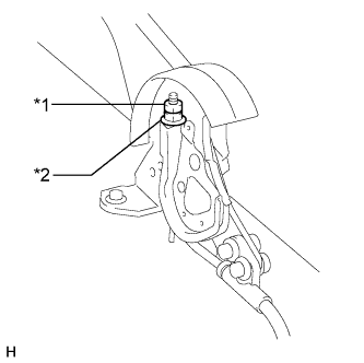
Text in Illustration *1 Lock Nut *2 No. 1 Parking Brake Cable Adjusting Nut Loosen the lock nut.
-
Turn the No. 1 parking brake cable adjusting nut until the lever travel is correct.
-
Tighten the lock nut.
- Torque:
- 5.2 N*m { 53 kgf*cm, 46 in.*lbf }
Tech Tips
If the lever travel cannot be fully adjusted with this procedure, proceed to the Adjust Parking Brake Turn Buckle procedure.
-
-
CONNECT CABLE TO NEGATIVE BATTERY TERMINAL
-
PERFORM INITIALIZATION
-
Perform initialization Click here.
Note
Certain systems need to be initialized after disconnecting and reconnecting the cable to the negative (-) battery terminal.
-
-
CHECK SPEED SENSOR SIGNAL
-
w/ Rear Differential Lock
Check the speed sensor signal Click here.
-
w/o VSC:
Check the speed sensor signal Click here.
-
w/ VSC:
Check the speed sensor signal Click here.
-