COMBUSTION TYPE POWER HEATER SYSTEM, Diagnostic DTC:047,048 and 049
| DTC Code | DTC Name |
|---|---|
| 047 | Short in Heater Fuel Pump Circuit |
| 048 | Heater Fuel Pump Malfunction |
| 049 | Heater Fuel Pump Output Error |
DESCRIPTION
DTC Code |
DTC Detection Condition |
Trouble Area |
|---|---|---|
047 |
A short is detected in the heater pump assembly circuit. |
|
048 |
Operation stop of the heater pump assembly is detected (open in the circuit). |
|
049 |
An error is detected in the output to the heater pump assembly. |
|
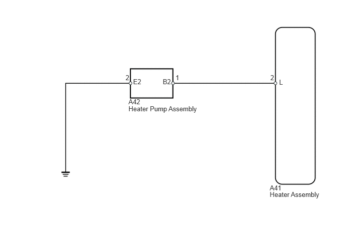
WIRING DIAGRAM
PROCEDURE
CHECK HARNESS AND CONNECTOR (HEATER ASSEMBLY - HEATER PUMP ASSEMBLY)
-
Disconnect the A41 heater connector.
Disconnect the A42 pump connector.
Measure the resistance according to the value(s) in the table below.
Standard Resistance
Tester Connection
Condition
Specified Condition
A41-2 (L) - A42-1 (B2)
Always
Below 1 Ω
A41-2 (L) - Body ground
Always
10 kΩ or higher
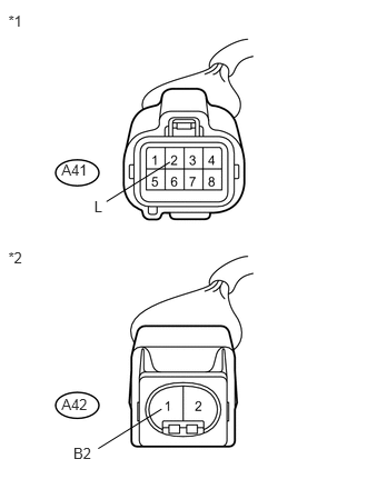
Table 1. Text in Illustration *1
Front view of wire harness connector
(to Heater Assembly)
*2
Front view of wire harness connector
(to Heater Pump Assembly)
REPAIR OR REPLACE HARNESS OR CONNECTOR
-
CHECK HARNESS AND CONNECTOR (HEATER PUMP ASSEMBLY - BODY GROUND)
-
Disconnect the A42 pump connector.
Measure the resistance according to the value(s) in the table below.
Standard Resistance
Tester Connection
Condition
Specified Condition
A42-2 (E2) - Body ground
Always
Below 1 Ω
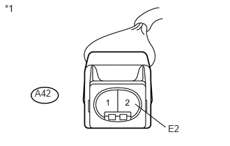
Table 2. Text in Illustration *1
Front view of wire harness connector
(to Heater Pump Assembly)
REPAIR OR REPLACE HARNESS OR CONNECTOR
-
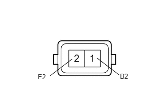
INSPECT HEATER PUMP ASSEMBLY
-
Remove the heater pump assembly with the fuel hose still connected (Click here).
Measure the resistance according to the value(s) in the table below.
Standard Resistance
Tester Connection
Condition
Specified Condition
1 (B2) - 2 (E2)
Always
9 to 12 Ω
Apply battery voltage to the heater pump assembly and check the pressure of the hose by hand.
OK
Measurement Condition
Specified Condition
Battery positive (+) → Terminal 1
Battery negative (-) → Terminal 2
Pressure is applied to the hose
Note:This inspection must be done quickly (within 10 seconds) to prevent damage to the heater pump assembly.
Always switch the voltage on and off on the battery side, not the heater pump assembly side.
Keep the heater pump assembly as far away from the battery as possible.
-