INTAKE MANIFOLD REMOVAL
CAUTION / NOTICE / HINT
The necessary procedures (adjustment, calibration, initialization or registration) that must be performed after parts are removed and installed, or replaced during intake manifold removal/installation are shown below.
| Replaced Part or Performed Procedure | Necessary Procedure | Effects/Inoperative when Necessary Procedure not Performed | Link |
|---|---|---|---|
|
Inspection After Repair |
|
Click here for Rear Air Fuel Ratio Sensor Click here for Rear Heated Oxygen Sensor |
PROCEDURE
-
REMOVE THROTTLE BODY WITH MOTOR ASSEMBLY
-
REMOVE INTERCOOLER ASSEMBLY
-
REMOVE FRONT WIPER MOTOR AND LINK ASSEMBLY
-
REMOVE OUTER COWL TOP PANEL SUB-ASSEMBLY (for LHD)
-
REMOVE OUTER COWL TOP PANEL SUB-ASSEMBLY (for RHD)
-
REMOVE PURGE VALVE (PURGE VSV)
-
REMOVE AIR CLEANER CAP WITH AIR CLEANER HOSE
-
REMOVE AIR CLEANER FILTER ELEMENT SUB-ASSEMBLY
-
Remove the air cleaner filter element sub-assembly from the air cleaner case sub-assembly.
-
-
REMOVE AIR CLEANER CASE SUB-ASSEMBLY
-
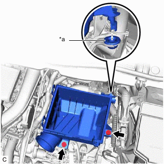
*a Air Cleaner Support Remove the 2 bolts and air cleaner case sub-assembly.
Note
Make sure the air cleaner support remains attached to the vehicle body.
-
-
DISCONNECT NO. 5 INTERCOOLER COOLING WATER HOSE
-
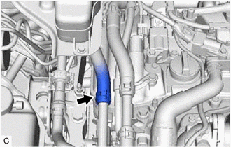
Slide the clip and disconnect the No. 5 intercooler cooling water hose from the No. 3 Intercooler cooling water pipe.
-
-
DISCONNECT NO. 6 INTERCOOLER COOLING WATER HOSE
-
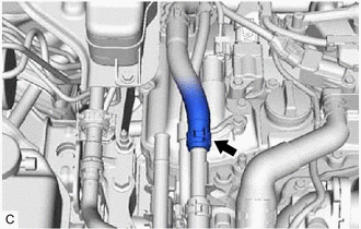
Slide the clip and disconnect the No. 6 intercooler cooling water hose from the No. 2 Intercooler cooling water pipe.
-
-
DISCONNECT ENGINE WIRE
-

Bolt 
Connector Disconnect the 3 sensor wire connectors.
-
Disengage the wire harness clamp from the wire harness bracket.
-
Remove the 2 bolts from the wire harness bracket.
-
Remove the bolt and disconnect the sensor wire from the intercooler support bracket sub-assembly.
-
Disengage the clamp and remove the sensor wire from the intercooler support bracket sub-assembly.
-
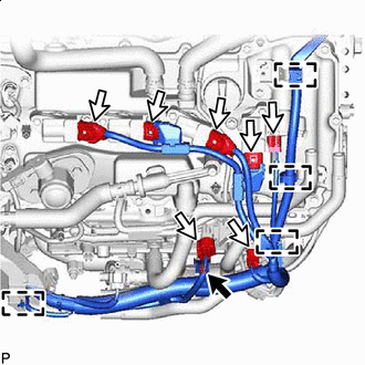
Bolt Connector Disconnect the 7 connectors.
-
Disengage the 4 wire harness clamps.
-
Remove the bolt.
-
Bolt Connector 
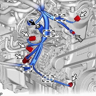
Ground Bolt Disconnect the 5 connectors.
-
Disengage the 4 wire harness clamps.
-
Remove the ground bolt.
-
Remove the bolt.
-
-
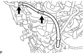
REMOVE NO. 2 WATER BY-PASS PIPE
-
Remove the 3 bolts and No. 2 water by-pass pipe from the cylinder head cover sub-assembly and bracket.
-
-
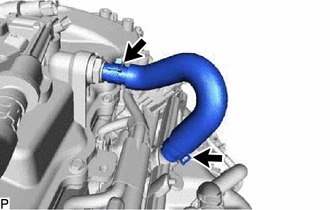
DISCONNECT NO. 2 VACUUM TRANSMITTING HOSE ASSEMBLY
-
Disconnect the No. 2 vacuum transmitting hose assembly from the vacuum pump assembly and cylinder head cover sub-assembly.
-
-
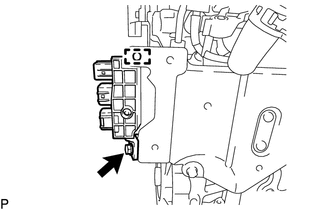
REMOVE NO. 1 TURBO PRESSURE SENSOR
-
DISCONNECT VACUUM TRANSMITTING HOSE ASSEMBLY
-
Disconnect the vacuum transmitting hose assembly from the vacuum regulating valve assembly.
-
-
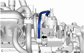
REMOVE NO. 2 VENTILATION HOSE
-
Slide the 2 clips and remove the No. 2 ventilation hose from the intake manifold and PCV valve (ventilation valve sub-assembly).
-
-
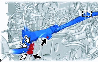
DISCONNECT WATER BY-PASS HOSE
-
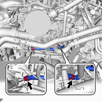
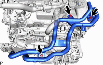
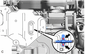
*1 No. 1 Water By-pass Hose *2 No. 2 Water By-pass Hose Slide the clip and disconnect the No. 2 water by-pass hose from the No. 1 water by-pass pipe.
-
Slide the clip and disconnect the No. 1 water by-pass hose from the cylinder head sub-assembly.
-
-
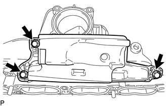
REMOVE INTAKE MANIFOLD
-
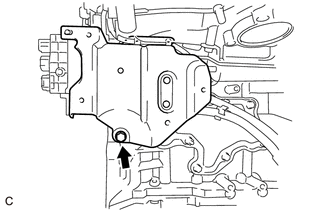
Remove the bolt and disconnect the intercooler support bracket sub-assembly from the cylinder block sub-assembly.
-
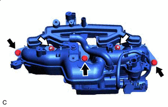
Bolt Nut Remove the 3 bolts, 2 nuts and intake manifold from the cylinder head sub-assembly.
-
Remove the 2 nuts and the manifold thermostat from the intercooler support bracket sub-assembly.
-
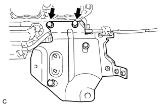
Remove the 2 bolts and intercooler support bracket sub-assembly from the intake manifold.
Note
Put matchmarks on the intercooler support bracket sub-assembly so that it can be installed to its original position.
-
Remove the bolt and wire harness clamp bracket from the intake manifold.
-
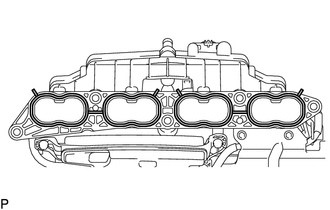
Remove the 2 No. 1 intake manifold to head gaskets from the intake manifold.
-
-
REMOVE NO. 2 FUEL VAPOR FEED HOSE
-
Slide the clip and remove the No. 2 fuel vapor feed hose from the intake manifold.
-
-
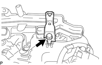
REMOVE BRACKET
-
Remove the bolt and bracket from the intake manifold.
-
-
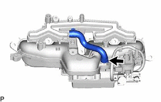
REMOVE NO. 3 VACUUM TRANSMITTING HOSE ASSEMBLY
-
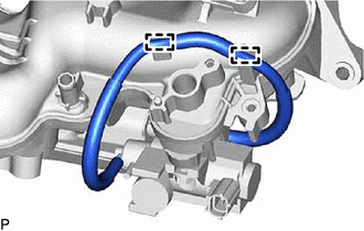
Disengage the No. 3 vacuum transmitting hose assembly from the intake manifold.
-
Remove the No. 3 vacuum transmitting hose assembly from the vacuum surge tank and vacuum regulating valve assembly.
-
-
REMOVE VACUUM REGULATING VALVE ASSEMBLY
-
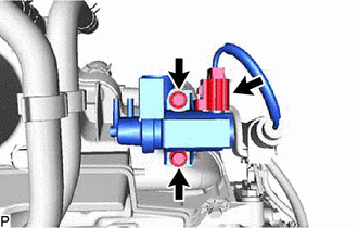
Disconnect the vacuum regulating valve assembly connector.
-
Remove the 2 bolts and vacuum regulating valve assembly from the intake manifold.
-
-
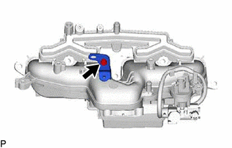
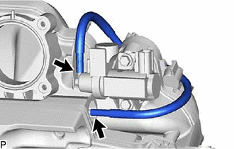
REMOVE NO. 4 VACUUM TRANSMITTING HOSE ASSEMBLY
-
Remove the No. 4 vacuum transmitting hose assembly from the intake manifold and vacuum surge tank.
-
-
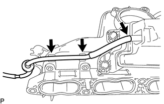
REMOVE VACUUM SURGE TANK
-
Remove the 3 bolts and vacuum surge tank from the intake manifold.
-