VEHICLE STABILITY CONTROL SYSTEM Downhill Assist Control Indicator Light does not Come ON
| DTC Code | DTC Name |
|---|---|
| Downhill Assist Control Indicator Light does not Come ON |
DESCRIPTION
Even if the downhill assist control switch is pressed, the downhill assist control indicator light blinks and downhill assist control does not activate under the following conditions:
Gear position is not R.
The brake system is malfunctioning.
The vehicle speed is 25 km/h (15 mph) or more.
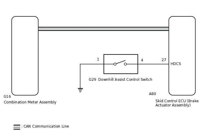
WIRING DIAGRAM
CAUTION / NOTICE / HINT
When replacing the skid control ECU (brake actuator assembly), perform zero point calibration.
PROCEDURE
CHECK CAN COMMUNICATION SYSTEM
Check if CAN communication system DTCs are output.
for LHD with Central Gateway ECU:Click here
for RHD with Central Gateway ECU:Click here
for LHD without Central Gateway ECU:Click here
for RHD without Central Gateway ECU:Click here
Result
Proceed to
DTC is not output
DTC is output (for LHD with Central Gateway ECU)
DTC is output (for RHD with Central Gateway ECU)
DTC is output (for LHD without Central Gateway ECU)
DTC is output (for RHD without Central Gateway ECU)
CHECK HARNESS AND CONNECTOR (HDCS TERMINAL)
Turn the ignition switch off.
Disconnect the A80 skid control ECU (brake actuator assembly) connector.
-
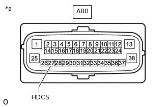
*a
Front view of wire harness connector
(to Skid Control ECU [Brake Actuator Assembly])
Measure the resistance according to the value(s) in the table below.
Standard Resistance
Tester Connection
Switch Condition
Specified Condition
A80-27 (HDCS) - Body ground
Downhill assist control switch is pushed
Below 1 Ω
A80-27 (HDCS) - Body ground
Downhill assist control switch is not pushed
10 kΩ or higher
Result
Proceed to
OK
NG
NG INSPECT DOWNHILL ASSIST CONTROL SWITCHClick here
PERFORM ACTIVE TEST USING GTS (DOWNHILL ASSIST CONTROL LIGHT)
Reconnect the A80 skid control ECU (brake actuator assembly) connector.
Connect the GTS to the DLC3.
Turn the ignition switch to ON.
Turn the GTS on.
Enter the following menus: Chassis / ABS/VSC/TRC / Data List.
According to the display on the GTS, perform the Active Test.
When performing the ABS Warning Light Active Test, check Downhill assist control indicator light in the Data List.
Chassis > ABS/VSC/TRC > Active Test
Tester Display
Measurement Item
Control Range
Diagnostic Note
Downhill Assist Control Light
Downhill assist control indicator light
Indicator light OFF/ON
Observe combination meter
Vehicle condition: Vehicle stopped
Chassis > ABS/VSC/TRC > Data List
Tester Display
Measurement Item
Range
Normal Condition
Diagnostic Note
Downhill Assist Control Light
Downhill assist control indicator light
ON or OFF
OFF: Downhill assist control indicator light off
ON: Downhill assist control indicator light on
w/ Downhill Assist Control:
The item is displayed on the GTS but not used.
OFF: Always
Chassis > ABS/VSC/TRC > Active Test
Active Test Display
Downhill Assist Control Light
Data List Display
Downhill Assist Control Light
Result
Result
Proceed to
Downhill assist control indicator light in the Data List does not change using the Active Test
A
Downhill assist control indicator light in the Data List turns ON/OFF using the Active Test
B
INSPECT COMBINATION METER ASSEMBLY
Turn the ignition switch off.
Perform Active Test of the combination meter assembly using the GTS.
Check the combination meter assembly.
Body Electrical > Combination Meter > Active Test
Tester Display
Indicat. Downhill Assist Control
OK
The Downhill assist control indicator light turns on or off in accordance with the GTS.
Result
Proceed to
OK
NG
INSPECT DOWNHILL ASSIST CONTROL SWITCH
Turn the ignition switch off.
Remove the downhill assist control switch.
Inspect the downhill assist control switch.
Result
Result
OK
NG
CHECK HARNESS AND CONNECTOR (BRAKE ACTUATOR ASSEMBLY - DOWNHILL ASSIST CONTROL SWITCH)
Measure the resistance according to the value(s) in the table below.
Standard Resistance
Tester Connection
Condition
Specified Condition
A80-27 (HDCS) - G29-4
Always
Below 1 Ω
A80-27 (HDCS) or G29-4 - Body ground
Always
10 kΩ or higher
G29-1 - Body ground
Always
Below 1 Ω
Result
Result
OK
NG
NG REPAIR OR REPLACE HARNESS OR CONNECTOR