MULTI-MODE MANUAL TRANSAXLE ASSEMBLY REMOVAL
PROCEDURE
CLUTCH POSITION ADJUSTMENT
DRAIN ENGINE COOLANT
DRAIN MANUAL TRANSAXLE OIL
DISCONNECT FRONT FENDER LINER LH
-
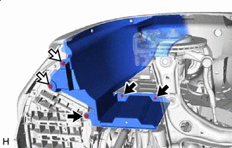

Bolt

Screw
Remove the 2 screws and 3 bolts to disconnect the front fender liner LH.
-
REMOVE FRONT EXHAUST PIPE ASSEMBLY
REMOVE FRONT DRIVE SHAFT ASSEMBLY
REMOVE AIR CLEANER CAP SUB-ASSEMBLY
REMOVE CLUTCH ACTUATOR ASSEMBLY
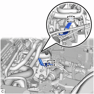
DISCONNECT NO. 3 ENGINE WIRE
-
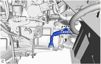
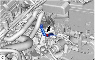
Disengage the clamp to disconnect the No. 3 engine wire from the wire harness clamp bracket.
-
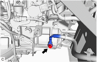
Remove the bolt and disconnect the No. 3 engine wire from the multi-mode manual transaxle assembly.
-
DISCONNECT ENGINE ROOM MAIN WIRE
-
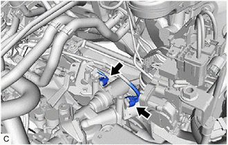
*a
Select Stroke Sensor Connector
*b
Park/Neutral Position Switch Assembly Connector
Disconnect the select stroke sensor connector.
Disconnect the park/neutral position switch assembly connector.
-
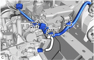
Disengage the 3 clamps to disconnect the engine room main wire.
-
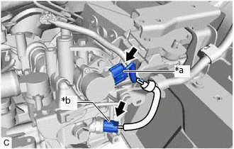
DISCONNECT ENGINE WIRE
-
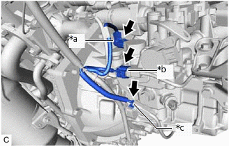
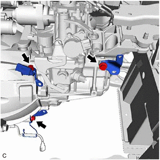
*a
Shift Stroke Sensor Connector
*b
Back-up Light Switch Assembly Connector
*c
Transmission Revolution Sensor Connector
Disconnect the shift stroke sensor connector.
Disconnect the back-up light switch assembly connector.
Disconnect the transmission revolution sensor connector.
-
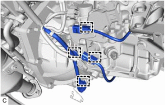
Disengage the 4 clamps to disconnect the engine wire.
-
Disengage the 2 clamps to disconnect the engine wire.
-
Remove the bolt and wire harness clamp bracket from the shift and select actuator assembly.
-
Disconnect the 2 shift and select actuator assembly connectors.
-
REMOVE WIRE HARNESS CLAMP BRACKET
-
Remove the 3 bolts and 3 wire harness clamp brackets from the multi-mode manual transaxle assembly.
-
REMOVE STARTER ASSEMBLY
REMOVE FLYWHEEL HOUSING SIDE COVER
SUPPORT ENGINE ASSEMBLY
Support the engine assembly with an engine lifter.
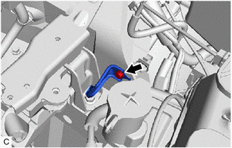
REMOVE ENGINE MOVING CONTROL ROD
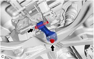
Remove the 2 bolts and engine moving control rod.
DISCONNECT NO. 2 RADIATOR HOSE
REMOVE FAN SHROUD ASSEMBLY
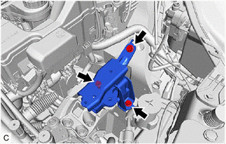
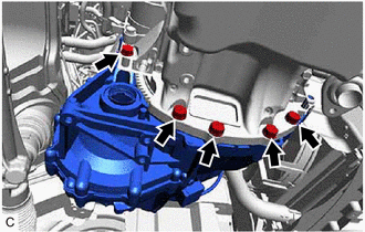
REMOVE ENGINE MOVING CONTROL ROD BRACKET
Remove the 3 bolts and the engine moving control rod bracket.
SUPPORT MULTI-MODE MANUAL TRANSAXLE ASSEMBLY
Support the multi-mode manual transaxle assembly with a transmission jack.
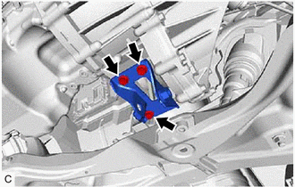
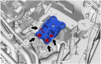
REMOVE ENGINE MOUNTING INSULATOR LH
-
Remove the 3 bolts from the engine mounting bracket LH.
-
Remove the bolt and wire harness clamp bracket.
-
Remove the 3 bolts and engine mounting insulator LH.
-
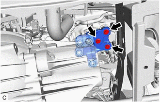
REMOVE ENGINE MOUNTING BRACKET LH
-
Remove the 4 bolts and engine mounting bracket LH from the multi-mode manual transaxle assembly.
-
REMOVE MULTI-MODE MANUAL TRANSAXLE ASSEMBLY
-
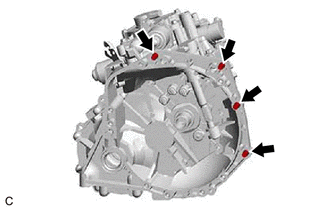
Remove the 4 bolts.
-
Remove the 5 bolts and multi-mode manual transaxle assembly from the engine assembly.
Note:To prevent damage to the 2 knock pins, do not pry between the multi-mode manual transaxle assembly and engine assembly.
Do not apply excessive force to the multi-mode manual transaxle assembly as this will break the input shaft.
Be careful not to damage the radiator assembly when removing the multi-mode manual transaxle assembly.
-