ENTRY AND START SYSTEM(for Entry Function) Back Door Entry Unlock Function does not Operate
| DTC Code | DTC Name |
|---|---|
| Back Door Entry Unlock Function does not Operate |
DESCRIPTION
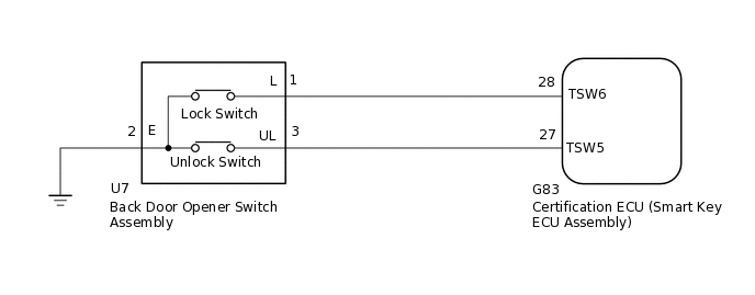
If the entry unlock function does not operate for the back door only, but the entry lock function operates, the request code is being transmitted properly from the back door. In this case, there may be a problem related to the unlock switch (connection between the back door opener switch assembly and certification ECU [smart key ECU assembly]).
WIRING DIAGRAM
CAUTION / NOTICE / HINT
The entry and start system (for Entry Function) uses the LIN communication system and CAN communication system. Inspect the communication function by following How to Proceed with Troubleshooting (Click here). Troubleshoot the entry and start system (for Entry Function) after confirming that the communication systems are functioning properly.
When using the GTS with the vehicle power switch off, connect the GTS to the vehicle and turn a courtesy light switch on and off at intervals of 1.5 seconds or less until communication between the GTS and the vehicle begins. Then select the Model Code "KEY REGIST" under manual mode and enter the following menus: Body Electrical / Entry&Start. While using the GTS, periodically turn a courtesy light switch on and off at intervals of 1.5 seconds or less to maintain communication between the GTS and the vehicle.
Check that there are no electrical key transmitter sub-assemblies in the vehicle.
Before replacing the certification ECU (smart key ECU assembly), refer to the entry and start system (for Entry Function) precaution.
After repair, confirm that no DTCs are output by performing "DTC Output Confirmation Operation".
PROCEDURE
CHECK POWER DOOR LOCK OPERATION
When the door control switch on the multiplex network master switch assembly is operated, check that the doors unlock and lock according to the switch operation.
Result
Proceed to
Door locks operate normally
Door locks do not operate
READ VALUE USING GTS (B-DR OPENING OPERATION)
Connect the GTS to the DLC3.
Turn the power switch on (IG).
Turn the GTS on.
Enter the following menus: Body Electrical / Entry&Start / Data List.
Read the Data List according to the display on the GTS.
Body Electrical > Entry&Start > Data List
Tester Display
Measurement Item
Range
Normal Condition
Diagnostic Note
B-Dr Opening Operation
Back door opening operation
Long, Twice, OFF
Customization status displayed
-
Body Electrical > Entry&Start > Data List
Tester Display
B-Dr Opening Operation
Result
Proceed to
Customize setting is Long or Twice
Customize setting is OFF
Customize setting is OFF PERFORM CUSTOMIZE SETTING (Proceed to Customize Parameters)
READ VALUE USING GTS (TR/B DOOR UNLOCK SW)
Read the Data List according to the display on the GTS.
Body Electrical > Entry&Start > Data List
Tester Display
Measurement Item
Range
Normal Condition
Diagnostic Note
Tr/B-Door Unlock SW
Back door opener switch (unlock switch)
ON or OFF
ON: Back door opener switch (unlock switch) pushed
OFF: Back door opener switch (unlock switch) not pushed
Displays whether the back door opener switch (unlock switch) is on or off.
Use this Data List item to help determine if there is a switch malfunction when the back door unlock function does not operate.
Body Electrical > Entry&Start > Data List
Tester Display
Tr/B-Door Unlock SW
OK
The GTS display changes correctly in response to the operation of the back door opener switch assembly.
Result
Proceed to
OK
NG
OK REPLACE CERTIFICATION ECU (SMART KEY ECU ASSEMBLY)
CHECK HARNESS AND CONNECTOR (BACK DOOR OPENER SWITCH ASSEMBLY - CERTIFICATION ECU)
Disconnect the U7 back door opener switch assembly connector.
Disconnect the G83 certification ECU (smart key ECU assembly) connector.
Measure the resistance according to the value(s) in the table below.
Standard Resistance
Tester Connection
Condition
Specified Condition
U7-3 (UL) - G83-27 (TSW5)
Always
Below 1 Ω
U7-2 (E) - Body ground
Always
Below 1 Ω
U7-3 (UL) or G83-27 (TSW5) - Body ground
Always
10 kΩ or higher
Result
Proceed to
OK
NG
NG REPAIR OR REPLACE HARNESS OR CONNECTOR
INSPECT BACK DOOR OPENER SWITCH ASSEMBLY (UNLOCK SWITCH)
-
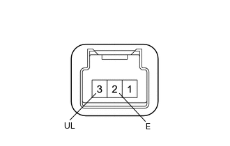
Remove the back door opener switch assembly.
Measure the resistance according to the value(s) in the table below.
Standard Resistance
Tester Connection
Condition
Specified Condition
3 (UL) - 2 (E)
No switch pushed
10 kΩ or higher
3 (UL) - 2 (E)
Unlock switch pushed
Below 1 Ω
Result
Proceed to
OK
NG
OK REPLACE CERTIFICATION ECU (SMART KEY ECU ASSEMBLY)
-