INSTRUMENT PANEL SAFETY PAD REMOVAL
PROCEDURE
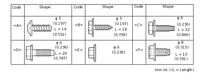
TABLE OF BOLT, SCREW AND NUT
Tip:All bolts, screws and nuts relevant to installing and removing the instrument panel are shown along with their alphabet code in the table below.
PRECAUTION
Note:After turning the ignition switch off, waiting time may be required before disconnecting the cable from the battery terminal. Therefore, make sure to read the disconnecting the cable from the battery terminal notice before proceeding with work.
DISCONNECT CABLE FROM NEGATIVE BATTERY TERMINAL
Disable the auto tilt away function by changing the customize parameter (Click here).
Note:Record the current customize parameter setting (whether the auto tilt away function is enabled or disabled) in order to restore the current setting after finishing the operation.
Tip:Performing the above operation causes the auto tilt away function to be disabled when the engine switch is turned off.
Turn the engine switch on (IG). Operate the tilt and telescopic switch to fully extend and lower the steering column assembly.
Turn the engine switch off and disconnect the cable from the negative (-) battery terminal.
CAUTION:Wait at least 90 seconds after disconnecting the cable from the negative (-) battery terminal to disable the SRS system.
Note:When disconnecting the cable, some systems need to be initialized after the cable is reconnected.
REMOVE HEADLIGHT DIMMER SWITCH ASSEMBLY
REMOVE REAR CONSOLE BOX ASSEMBLY
REMOVE DOOR SCUFF PLATE ASSEMBLY LH
REMOVE DOOR SCUFF PLATE ASSEMBLY RH
Tip:Use the same procedure described for the LH side.
REMOVE COWL SIDE TRIM BOARD LH
REMOVE COWL SIDE TRIM BOARD RH
Tip:Use the same procedure described for the LH side.
REMOVE FRONT DOOR OPENING TRIM WEATHERSTRIP LH
REMOVE FRONT DOOR OPENING TRIM WEATHERSTRIP RH
Tip:Use the same procedure described for the LH side.
REMOVE FRONT NO. 1 ASSIST GRIP PLUG LH
REMOVE FRONT NO. 1 ASSIST GRIP PLUG RH
Tip:Use the same procedure described for the LH side.
REMOVE NO. 1 ASSIST GRIP
REMOVE FRONT PILLAR GARNISH LH
REMOVE FRONT PILLAR GARNISH RH
Tip:Use the same procedure described for the LH side.
REMOVE INSTRUMENT SIDE PANEL LH
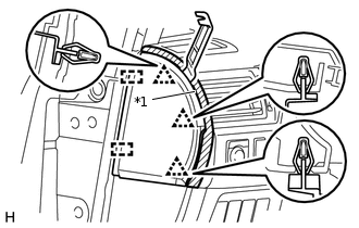
*1
Protective Tape
Put protective tape around the instrument side panel.
Using a moulding remover, detach the 3 clips and 2 guides and remove the instrument side panel.
REMOVE NO. 2 SWITCH HOLE BASE
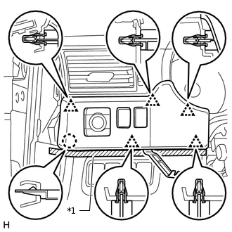
*1
Protective Tape
Put protective tape around the No. 2 switch hole base.
Using a moulding remover, detach the 5 clips and claw.
Disconnect each connector and remove the No. 2 switch hole base.
REMOVE NO. 1 INSTRUMENT PANEL FINISH CUSHION
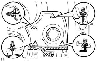
*1
Protective Tape
Put protective tape around the No. 1 instrument panel finish cushion.
Using a moulding remover, detach the 4 clips.
Disconnect the connector and remove the No. 1 instrument panel finish cushion.
REMOVE LOWER INSTRUMENT PANEL FINISH PANEL ASSEMBLY
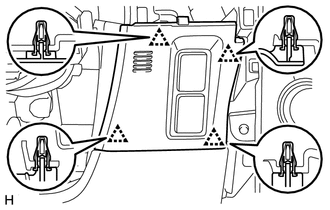
Detach the 4 clips.
Disconnect each connector and cooler thermistor and remove the instrument panel finish panel.
REMOVE INSTRUMENT CLUSTER FINISH PANEL SUB-ASSEMBLY
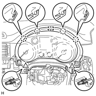
Detach the 4 claws, 2 clips and guide and remove the instrument cluster finish panel.
REMOVE NO. 1 INSTRUMENT PANEL REGISTER ASSEMBLY
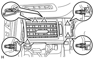
Detach the 5 clips and remove the No. 1 instrument panel register.
REMOVE COMBINATION METER ASSEMBLY
REMOVE LOWER INSTRUMENT PANEL FINISH PANEL SUB-ASSEMBLY
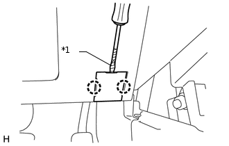
*1
Protective Tape
Using a screwdriver, detach the 2 claws and open the cover.
Tip:Tape the screwdriver tip before use.
-
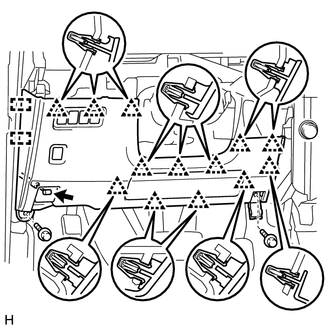
Remove the 2 bolts <C>.
Detach the 13 clips and 2 guides.
Disconnect each connector and cable and remove the lower instrument panel finish panel.
REMOVE LOWER NO. 1 INSTRUMENT PANEL AIRBAG ASSEMBLY
REMOVE INSTRUMENT SIDE PANEL RH
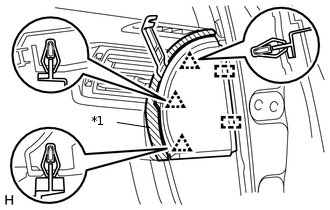
*1
Protective Tape
Put protective tape around the instrument side panel.
Using a moulding remover, detach the 3 clips and 2 guides and remove the instrument side panel.
REMOVE CENTER INSTRUMENT CLUSTER FINISH PANEL GARNISH
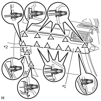
*1
Center Instrument Cluster Finish Panel Garnish
*2
Instrument Cluster Finish Panel Garnish
Detach the 13 clips and remove the center instrument cluster finish panel garnish together with the instrument cluster finish panel garnish.
REMOVE NO. 2 INSTRUMENT PANEL REGISTER ASSEMBLY
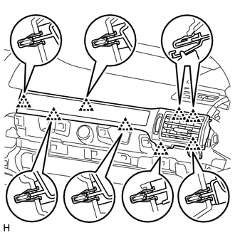
Detach the 8 clips and remove the No. 2 instrument panel register.
REMOVE LOWER INSTRUMENT COVER LH
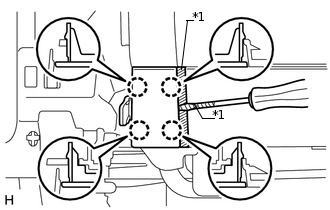
*1
Protective Tape
Put protective tape around the lower instrument cover.
Using a screwdriver, detach the 4 claws and remove the lower instrument cover.
Tip:Tape the screwdriver tip before use.
REMOVE LOWER NO. 2 INSTRUMENT PANEL AIRBAG ASSEMBLY
REMOVE INSTRUMENT PANEL BOX DOOR COVER
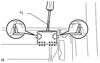
*1
Protective Tape
Tip:Use the same procedure for all instrument panel box door covers.
Using a screwdriver, detach the 2 claws and 2 guides and remove the instrument panel box door cover.
Tip:Tape the screwdriver tip before use.
REMOVE INSTRUMENT PANEL BOX ASSEMBLY
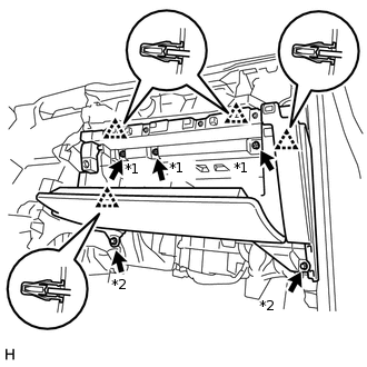
*1
Screw <B>
*2
Bolt <C>
Remove the 3 screws <B> and 2 bolts <C>.
Detach the 4 clips.
Disconnect each connector, detach the clamp and remove the instrument panel box.
REMOVE DRIVING SUPPORT SWITCH CONTROL ECU
REMOVE FOUR WHEEL DRIVE CONTROL ECU
REMOVE TELEMATICS TRANSCEIVER
REMOVE FRONT UPPER CONSOLE PANEL GARNISH
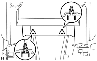
Detach the 2 clips and remove the front upper console panel garnish.
REMOVE MULTI-MEDIA MODULE RECEIVER ASSEMBLY
REMOVE MULTI-DISPLAY ASSEMBLY
REMOVE UPPER INSTRUMENT CLUSTER FINISH PANEL
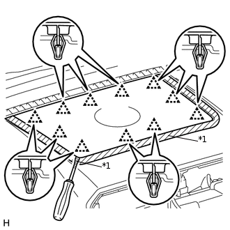
*1
Protective Tape
Put protective tape around the upper instrument cluster finish panel.
Using a screwdriver, detach the 11 clips and remove the upper instrument cluster finish panel.
Tip:Tape the screwdriver tip before use.
REMOVE FRONT NO. 4 SPEAKER ASSEMBLY
REMOVE NO. 1 INSTRUMENT PANEL SPEAKER PANEL SUB-ASSEMBLY
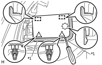
*1
Protective Tape
Put protective tape around the No. 1 instrument panel speaker panel.
Using a screwdriver, detach the 2 clips, claw and 2 guides and remove the No. 1 instrument panel speaker panel.
Tip:Tape the screwdriver tip before use.
REMOVE NO. 2 INSTRUMENT PANEL SPEAKER PANEL SUB-ASSEMBLY
Tip:Use the same procedure described for the No. 1 instrument panel speaker panel.
REMOVE FRONT NO. 2 SPEAKER ASSEMBLY
REMOVE FRONT NO. 3 SPEAKER ASSEMBLY
REMOVE FRONT SEAT ASSEMBLY LH
REMOVE FRONT SEAT ASSEMBLY RH
Tip:Use the same procedure described for the LH side.
REMOVE INSTRUMENT PANEL SAFETY PAD SUB-ASSEMBLY
Partially remove the floor carpet.
Tip:It is not necessary to fully remove the floor carpet. Partially remove it so that the No. 2 instrument panel wire can be removed in a later step.
Remove the 6 bolts <D> and nut <E>.
Remove the 2 passenger airbag bolts <F>.
Disconnect the connectors and detach the clamps and claws.
Detach the 2 guides and remove the instrument panel safety pad.
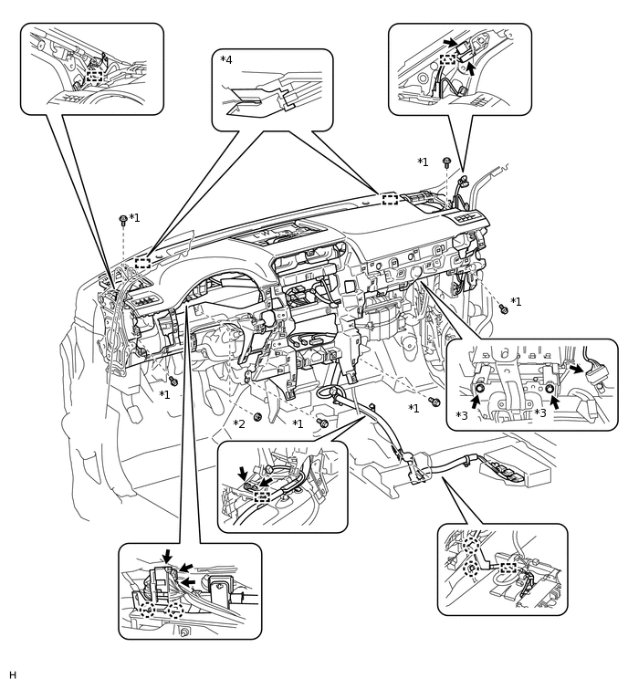
*1
Bolt <D>
*2
Nut <E>
*3
Bolt <F>
*4
Guide