STARTER (for 2.2 kW Type Bosch Made) INSPECTION
-
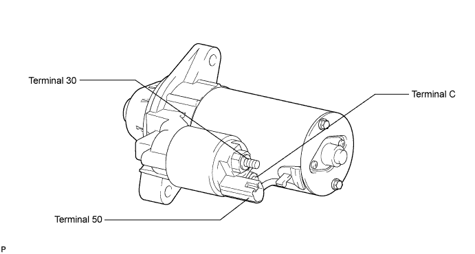
INSPECT STARTER ASSEMBLY
Note
These tests must be performed within 3 to 5 seconds to prevent the coil from burning out.
-
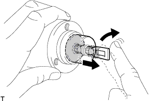
Perform pull-in test.
-
Remove the nut, and then disconnect the field coil core from terminal C.
-
Connect the battery to the magnet starter switch as shown in the illustration. Then check that the clutch pinion gear moves outward.
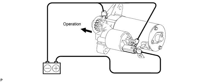
If the clutch pinion gear does not move, replace the magnet starter switch assembly.
-
-
Perform holding test.
-
When the battery is connected as above with the clutch pinion gear out, disconnect the negative (-) lead from terminal C. Check that the pinion gear remains out.
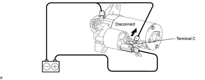
If the clutch pinion gear returns inward, replace the magnet starter switch assembly.
-
-
Inspect clutch pinion gear return.
-
Disconnect the negative (-) lead from the starter body. Check that the clutch pinion gear returns inward.
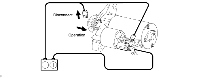
If the clutch pinion gear does not return inward, replace the magnet starter switch assembly.
-
-
Perform operation test without load.
-
Connect the field coil lead wire to terminal C with the nut.
- Torque:
- 8.0 N*m { 82 kgf*cm, 71 in.*lbf }
-
Mount the starter in a vise between aluminum plates.
-
Connect the battery and ammeter to the starter as shown in the illustration.
-
Check that the starter rotates smoothly and steadily while the pinion gear is moving outward. Then measure the current.
Standard current 123 A or less at 11.5 V 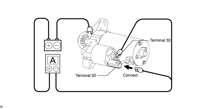
If the result is not as specified, replace the starter assembly.
-
-
-
INSPECT STARTER ARMATURE ASSEMBLY
-
Measure the resistance.
-
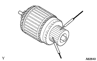
Measure the resistance between the segments of the commutator.
Standard resistance Below 1.7 Ω If the result is not as specified, replace the armature assembly.
-
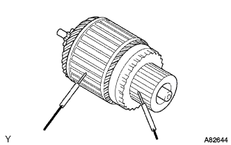
Measure the resistance between a segment of the commutator and armature coil core.
Standard resistance 10 kΩ or higher If the result is not as specified, replace the armature assembly.
-
-
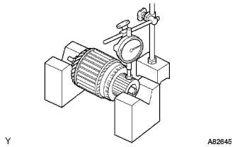
Inspect the commutator circle runout.
-
Place the commutator on V-blocks.
-
Using a dial indicator, measure the circle runout.
Standard runout 0.02 mm (0.0008 in.) Maximum runout 0.04 mm (0.0016 in.) If the runout is greater than the maximum, replace the armature assembly.
-
-
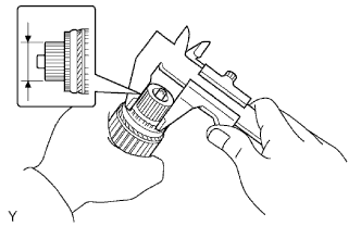
Using a vernier caliper, measure the commutator diameter.
Standard diameter 32.2 mm (1.2783 in.) Minimum diameter 31.1 mm (1.2347 in.) If the diameter is less than the minimum, replace the armature assembly.
-
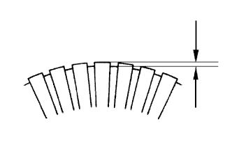
Using a vernier caliper, measure the undercut depth of the commutator.
Standard depth 0.9 mm (0.0354 in.) Minimum depth 0.4 mm (0.0157 in.) If the depth is less than the minimum, replace the armature assembly.
-
-
INSPECT STARTER BRUSH HOLDER ASSEMBLY
-
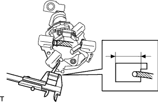
Using a vernier caliper, measure the brush length.
Standard length 14.0 mm (0.5558 in.) Minimum length 9.0 mm (0.3543 in.) If the length is less than the minimum, replace the starter brush holder assembly.
-
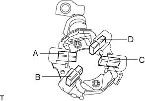
Check the brush holder.
-
Measure the resistance between the brushes.
Standard resistance Tester Connection Specified Condition A - B 10 kΩ or higher A - C 10 kΩ or higher A - D Below 1 Ω B - C Below 1 Ω B - D 10 kΩ or higher C - D 10 kΩ or higher If the result is not as specified, replace the starter brush holder assembly.
-
-
-
INSPECT STARTER CLUTCH SUB-ASSEMBLY
-
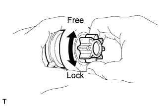
Check the starter clutch pinion gear.
-
Rotate the pinion gear clockwise and check that it turns freely. Try to rotate the pinion gear counterclockwise and check that it locks.
If the result is not as specified, replace the starter clutch sub-assembly.
-
-
-
INSPECT MAGNET STARTER SWITCH ASSEMBLY
-
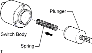
Check the plunger.
-
Install the plunger and spring onto the switch body.
-
Push in the plunger and check that it returns quickly to its original position.
If the result is not as specified, replace the magnet starter switch assemby.
-
-
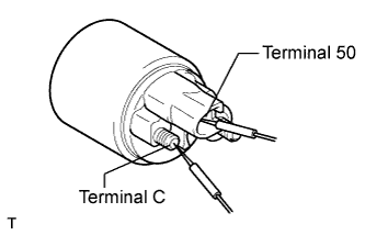
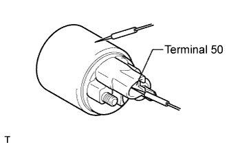
Check if the pull-in coil has an open circuit.
-
Measure the resistance between terminal 50 and terminal C.
Standard resistance Below 1 Ω If the result is not as specified, replace the magnet starter switch assembly.
-
-
Check if the hold-in coil has an open circuit.
-
Measure the resistance between terminal 50 and the switch body.
Standard resistance Below 2 Ω If the result is not as specified, replace the magnet starter switch.
-
-