CHARGING SYSTEM ON-VEHICLE INSPECTION
CAUTION / NOTICE / HINT
Note
If the battery is weak or if the engine is difficult to start, recharge the battery and perform inspections again before returning the vehicle to the customer.
PROCEDURE
-
CHECK BATTERY CONDITION
-
Check the battery for damage or deformation. If severe damage, deformation or leakage is found, replace the battery.
-
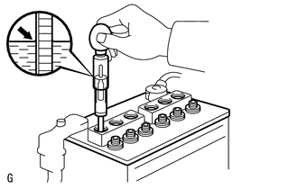
Check the electrolyte level in each cell.
-
If the electrolyte level is below the lower line, add distilled water to each cell. Then, recharge the battery and check the electrolyte specific gravity.
Standard Specific Gravity 1.25 to 1.29 at 20°C (68°F) -
If the electrolyte level is above the lower line, check the battery voltage when cranking the engine. If the battery voltage is less than 9.6 V, recharge or replace the battery.
Tech Tips
Before checking the battery voltage, turn off all the electrical systems (headlights, blower motor, rear window defogger, etc.).
-
-
Check the voltage.
-
Turn the engine switch off and turn on the headlights for 20 to 30 seconds. This will remove the surface charge from the battery.
-
Measure the battery voltage according to the value(s) in the table below.
Standard Voltage Tester Connection Condition Specified Condition Positive (+) terminal - Negative (-) terminal 20°C (68°F) 12.6 to 12.8 V If the result is not as specified, recharge or replace the battery.
-
-
-
REPLACE BATTERY
-
Replace the battery.
Note
w/ Stop and Start System:
For models with a stop and start system, replace the battery with an S-95 type or higher performance battery. Otherwise, the battery may deteriorate quickly or the engine may not even start.
Battery Type S-95 type or higher performance battery
-
-
INSPECT BATTERY TERMINAL, BATTERY STATE SENSOR ASSEMBLY (w/ Stop and Start System) AND FUSIBLE LINK AND FUSE
-
Check whether the battery terminals and engine wire harness are loose or corroded.
-
w/ Stop and Start System:
Check whether the battery state sensor assembly is deformed or cracked.
- Torque:
- Positive (+) Battery Terminal
- 5.4 N*m { 55 kgf*cm, 48 in.*lbf }
- Negative (-) Battery Terminal (Battery State Sensor Assembly)
- 5.4 N*m { 55 kgf*cm, 48 in.*lbf }
- Wire Harness
- 7.6 N*m { 77 kgf*cm, 67 in.*lbf }
-
w/o Stop and Start System:
Check that the battery terminals are not loose or corroded.
- Torque:
- Positive (+) battery terminal
- 5.4 N*m { 55 kgf*cm, 48 in.*lbf }
- Negative (-) battery terminal
- 5.4 N*m { 55 kgf*cm, 48 in.*lbf }
-
Measure the resistance of the fuses.
Standard Resistance Below 1 Ω If the result is not as specified, replace the fuse.
-
-
INSPECT V-RIBBED BELT
-
INSPECT GENERATOR WIRING
-
Visually check the generator wiring.
-
Check that the wiring is in good condition.
-
-
-
CHECK FOR ABNORMAL NOISE
-
Check for abnormal noises from the generator assembly.
-
Check that no abnormal noises are heard from the generator assembly while the engine is running.
If noise occurs, refer to Problem Symptoms Table.
-
-
-
INSPECT CHARGING CIRCUIT WITHOUT LOAD
-
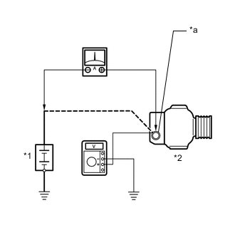
*1 Battery *2 Generator Assembly *a Terminal B Connect a voltmeter and an ammeter to the charging circuit as follows.
Tech Tips
If a battery/generator assembly tester is available, connect the tester to the charging circuit in accordance with the manufacturer's instructions.
-
Disconnect the wire from terminal B of the generator assembly and connect it to the negative (-) lead of the ammeter.
-
Connect the ammeter positive (+) lead to terminal B of the generator assembly.
-
Connect the voltmeter positive (+) lead to terminal B of the generator assembly.
-
Ground the voltmeter negative (-) lead.
-
-
Check the charging circuit.
-
Maintain the engine speed at 2000 rpm and check the readings on the ammeter and voltmeter.
Standard Current 10 A or higher Standard Voltage 13.2 to 14.8 V If the result is not as specified, repair or replace the generator assembly.
-
-
-
INSPECT CHARGING CIRCUIT WITH LOAD
-
With the engine running at 2000 rpm, turn the high beam headlights on and turn the heater blower switch to the "HI" position.
-
Check the reading on the ammeter.
Standard Current 30 A or higher If the result is not as specified, repair or replace the generator assembly.
Tech Tips
If the battery is fully charged, the reading will sometimes be less than the standard. If this is the case, add more electrical load (operate the wipers, rear window defogger, etc.) and check the reading on the ammeter again.
-
-
INSPECT CHARGING SYSTEM
-
Check the harness and connector.
-
Disconnect the C20 ECM connector.
-
Disconnect the C18 generator assembly connector.
-
w/ Stop and Start System:
Disconnect the A11 battery state sensor assembly connector.
-
Measure the resistance according to the value(s) in the table below.
Standard Resistance Tester Connection Condition Specified Condition C20-61 (LIN) - C18-2 (LIN) Always Below 1 Ω C20-61 (LIN) or C18-2 (LIN) - Body ground Engine switch off
(while LIN communication is stopped)
10 kΩ or higher C20-61 (LIN) - A11-2 (LIN1)* Always Below 1 Ω C20-61 (LIN) or A11-2 (LIN1) - Body ground* Engine switch off
(while LIN communication is stopped)
10 kΩ or higher
-
*: w/ Stop and Start System
If the result is not as specified, repair or replace the harness or connector.
-
-
-