CYLINDER HEAD GASKET INSTALLATION
CAUTION / NOTICE / HINT
PROCEDURE
INSTALL CYLINDER HEAD GASKET
-
*a
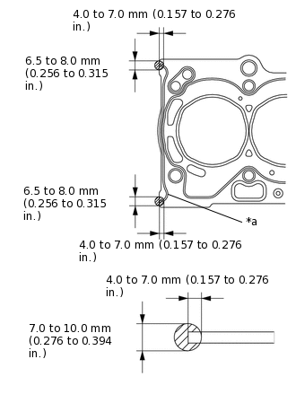
Bead
Apply seal packing to the new cylinder head gasket as shown in the illustration.
Seal packing
Toyota Genuine Seal Packing Black, Three Bond 1207B or equivalent
Note:Clean the sealing surfaces of the cylinder head gasket, cylinder head sub-assembly and cylinder block sub-assembly.
Install the cylinder head sub-assembly within 3 minutes and tighten the cylinder head set bolts within 15 minutes of applying seal packing.
Tip:Apply seal packing to the bead on the cylinder head gasket.
-
*a
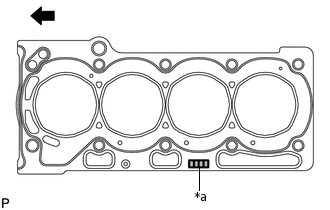
Lot No.

Engine Front
Place the cylinder head gasket on the cylinder block sub-assembly surface with the Lot No. stamp facing upward.
Note:Remove any oil from the contact surface.
Make sure that the cylinder head gasket is installed in the correct direction.
-
INSTALL CYLINDER HEAD SUB-ASSEMBLY
Apply a light coat of engine oil to the cylinder head set bolt threads and the area beneath the cylinder head set bolt heads that come in contact with the plate washers.
Install the cylinder head set bolts and plate washers to the cylinder head sub-assembly.
Note:Do not drop the plate washers into the cylinder head sub-assembly.
-
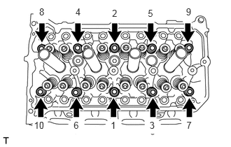
Using a 10 mm bi-hexagon wrench, uniformly install and tighten the 10 cylinder head set bolts and 10 plate washers in several steps and in the order shown in the illustration.
32 N*m
326 kgf*cm
24 ft.*lbf
-
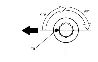
*a
Paint Mark
Engine Front
Mark the front side of the cylinder head set bolts with paint.
Tighten the cylinder head set bolts an additional 90°, then once more 90° as shown in the illustration.
Note:Do not tighten the same cylinder head set bolt twice consecutively.
Check that the paint mark is now at a 180° angle to the front.
-
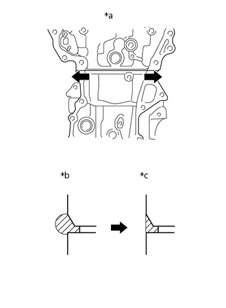
*a
Direction to wipe off
*b
Before wiping off
*c
After wiping off
Wipe off the seal packing seeped out from the contact surface between the cylinder head sub-assembly and cylinder block sub-assembly.
Note:Do not allow any seal packing to enter the cylinder head set bolt holes when wiping off the seal packing.
Tip:Be sure to wipe off the seal packing from inside to outside, in parallel to the joint line.
Perform "Inspection After Repair" after replacing the cylinder head sub-assembly.
INSTALL INTAKE MANIFOLD
INSTALL FUEL INJECTOR ASSEMBLY
INSTALL FUEL DELIVERY SPACER
INSTALL FUEL DELIVERY PIPE
INSTALL EXHAUST MANIFOLD CONVERTER SUB-ASSEMBLY (TWC: Front Catalyst)
INSTALL MANIFOLD STAY
INSTALL NO. 2 EXHAUST MANIFOLD HEAT INSULATOR
INSTALL NO. 1 EXHAUST MANIFOLD HEAT INSULATOR
INSTALL OIL LEVEL DIPSTICK GUIDE SUB-ASSEMBLY
INSTALL CAMSHAFT