INTAKE MANIFOLD INSTALLATION
PROCEDURE
-
INSTALL VACUUM SURGE TANK
-
Install the vacuum surge tank to the intake manifold with the 3 bolts.
- Torque:
- 10 N*m { 102 kgf*cm, 7 ft.*lbf }
-
-
INSTALL NO. 4 VACUUM TRANSMITTING HOSE ASSEMBLY
-
Install the No. 4 vacuum transmitting hose assembly to the intake manifold and vacuum surge tank.
-
-
INSTALL VACUUM REGULATING VALVE ASSEMBLY
-
Install the vacuum regulating valve assembly to the intake manifold with the 2 bolts.
- Torque:
- 10 N*m { 102 kgf*cm, 7 ft.*lbf }
-
Connect the vacuum regulating valve assembly connector.
-
-
INSTALL NO. 3 VACUUM TRANSMITTING HOSE ASSEMBLY
-
Install the No. 3 vacuum transmitting hose assembly to the vacuum surge tank and vacuum regulating valve assembly.
-
Engage the No. 3 vacuum transmitting hose assembly to the intake manifold.
-
-
INSTALL BRACKET
-
Install the bracket to the intake manifold with the bolt.
- Torque:
- 10 N*m { 102 kgf*cm, 7 ft.*lbf }
-
-
INSTALL NO. 2 FUEL VAPOR FEED HOSE
-
Install the No. 2 fuel vapor feed hose to the intake manifold and slide the clip to secure it.
-
-
INSTALL INTAKE MANIFOLD
-
When installing a new intercooler support bracket sub-assembly:
Temporarily install the intake manifold.
Note
If temporary installation is not performed, connecting parts may not be airtight as a result of incorrect positioning.
-
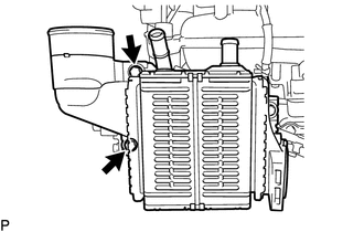
Temporarily install a new intercooler support bracket sub-assembly to the intake manifold with the 2 bolts.
-
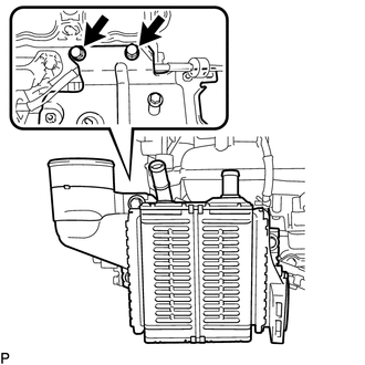
Temporarily install the intercooler assembly.
-
Tighten the 2 bolts of the intercooler support bracket sub-assembly.
- Torque:
- 10 N*m { 102 kgf*cm, 7 ft.*lbf }
-
Remove the 2 bolts and intercooler assembly from the intercooler support bracket sub-assembly.
-
-
When reusing the intercooler support bracket sub-assembly:
Align the matchmarks and install the intercooler support bracket sub-assembly with the 2 bolts.
- Torque:
- 10 N*m { 102 kgf*cm, 7 ft.*lbf }
-
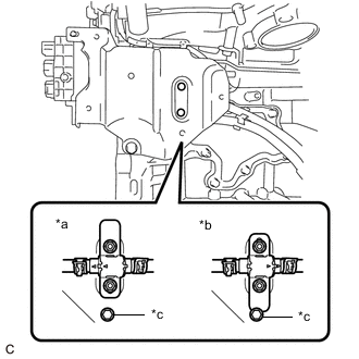
*a Correct *b Incorrect *c Stopper Install the manifold thermostat to the intercooler support bracket sub-assembly with the 2 nuts.
- Torque:
- 10 N*m { 102 kgf*cm, 7 ft.*lbf }
Note
Make sure that the manifold thermostat does not contact the stopper as shown in the illustration.
-
Install 2 new No. 1 intake manifold to head gaskets to the intake manifold.
-
Temporarily install the intake manifold with the 3 bolts and 2 nuts.
-
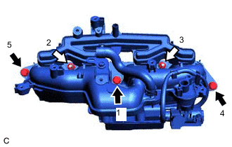

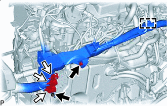
Bolt 
Nut Tighten the 3 bolts and 2 nuts in the order shown in the illustration.
- Torque:
- 21 N*m { 214 kgf*cm, 15 ft.*lbf }
-
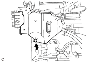
Connect the intercooler support bracket sub-assembly to the cylinder block sub-assembly with the bolt.
- Torque:
- 21 N*m { 214 kgf*cm, 15 ft.*lbf }
-
Install the wire harness clamp bracket to the intake manifold with the bolt.
- Torque:
- 10 N*m { 102 kgf*cm, 7 ft.*lbf }
-
-
CONNECT WATER BY-PASS HOSE
-
Connect the No. 1 water by-pass hose to the cylinder head sub-assembly and slide the clip to secure it.
-
Connect the No. 2 water by-pass hose to the No. 1 water by-pass pipe and slide the clip to secure it.
-
-
INSTALL NO. 2 VENTILATION HOSE
-
Install the No. 2 ventilation hose to the intake manifold and PCV valve (ventilation valve sub-assembly) and slide the 2 clips to secure it.
-
-
CONNECT VACUUM TRANSMITTING HOSE ASSEMBLY
-
Connect the vacuum transmitting hose assembly to the vacuum regulating valve assembly.
-
-
INSTALL NO. 1 TURBO PRESSURE SENSOR
-
CONNECT NO. 2 VACUUM TRANSMITTING HOSE ASSEMBLY
-
Connect the No. 2 vacuum transmitting hose assembly to the vacuum pump assembly and cylinder head cover sub-assembly.
-
-
INSTALL NO. 2 WATER BY-PASS PIPE
-
Install the No. 2 water by-pass pipe to the cylinder head cover sub-assembly and bracket with the 3 bolts.
- Torque:
- 10 N*m { 102 kgf*cm, 7 ft.*lbf }
-
-
CONNECT ENGINE WIRE
-
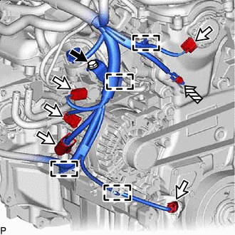
Bolt Connector 
Ground Bolt Install the bolt.
- Torque:
- 8.0 N*m { 82 kgf*cm, 71 in.*lbf }
-
Install the ground bolt.
- Torque:
- 8.5 N*m { 87 kgf*cm, 75 in.*lbf }
-
Engage the 4 wire harness clamps.
-
Connect the 5 connectors.
-
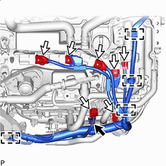
Bolt Connector Install the bolt.
- Torque:
- 8.0 N*m { 82 kgf*cm, 71 in.*lbf }
-
Engage the 4 wire harness clamps.
-
Connect the 7 connectors.
-
Connect the sensor wire to the intercooler support bracket sub-assembly.
-
Install the sensor wire to the intercooler support bracket sub-assembly with the bolt.
- Torque:
- 8.0 N*m { 82 kgf*cm, 71 in.*lbf }
-
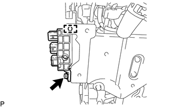
Bolt Connector Install the 2 bolts to the wire harness bracket.
- Torque:
- 8.0 N*m { 82 kgf*cm, 71 in.*lbf }
-
Engage the wire harness clamp from the wire harness bracket.
-
Connect the 3 sensor wire connectors.
-
-
CONNECT NO. 6 INTERCOOLER COOLING WATER HOSE
-
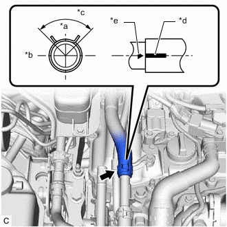
*a Up *b RH *c 90° *d Paint Mark *e Matchmark Connect the No. 6 intercooler cooling water hose to the No. 2 Intercooler cooling water pipe and slide the clip to secure it.
Tech Tips
-
Engage the clip within the area shown in the illustration.
-
Make sure that the paint mark of the No. 6 intercooler cooling water hose is positioned as shown in the illustration.
-
-
-
CONNECT NO. 5 INTERCOOLER COOLING WATER HOSE
-
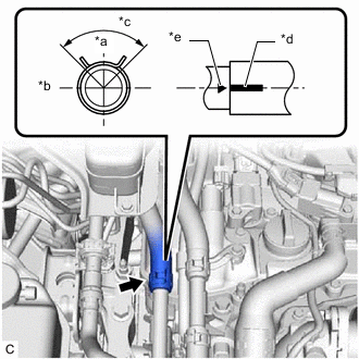
*a Up *b RH *c 90° *d Paint Mark *e Matchmark Connect the No. 5 intercooler cooling water hose to the No. 3 Intercooler cooling water pipe and slide the clip to secure it.
Tech Tips
-
Engage the clip within the area shown in the illustration.
-
Make sure that the paint mark of the No. 5 intercooler cooling water hose is positioned as shown in the illustration.
-
-
-
INSTALL AIR CLEANER CASE SUB-ASSEMBLY
-
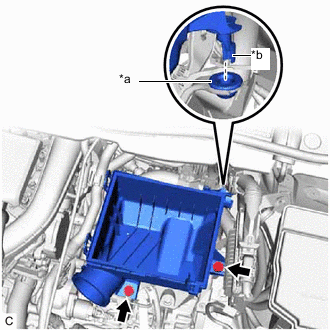
*a Air Cleaner Support *b Protrusion Fit the protrusion of the air cleaner case sub-assembly into the air cleaner support as shown in the illustration.
-
Install the air cleaner case sub-assembly with the 2 bolts.
- Torque:
- 5.0 N*m { 51 kgf*cm, 44 in.*lbf }
-
-
INSTALL AIR CLEANER FILTER ELEMENT SUB-ASSEMBLY
-
Install the air cleaner filter element sub-assembly to the air cleaner case sub-assembly.
-
-
INSTALL AIR CLEANER CAP WITH AIR CLEANER HOSE
-
INSTALL PURGE VALVE (PURGE VSV)
-
INSTALL OUTER COWL TOP PANEL SUB-ASSEMBLY (for LHD)
-
INSTALL OUTER COWL TOP PANEL SUB-ASSEMBLY (for RHD)
-
INSTALL FRONT WIPER MOTOR AND LINK ASSEMBLY
-
INSTALL INTERCOOLER ASSEMBLY
-
INSTALL THROTTLE BODY WITH MOTOR ASSEMBLY