MANUAL TRANSMISSION UNIT INSPECTION

PROCEDURE
-
INSPECT COUNTERSHAFT 5TH GEAR
-
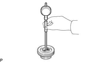
Using a cylinder gauge, measure the inside diameter of the countershaft 5th gear.
Standard inside diameter 38.015 to 38.040 mm (1.4967 to 1.4976 in.) Maximum inside diameter 38.040 mm (1.4976 in.) If the inside diameter is more than the maximum, replace the countershaft 5th gear.
-
-
INSPECT COUNTERSHAFT 5TH GEAR THRUST CLEARANCE
-
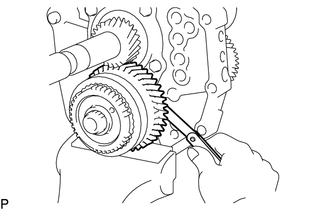
Using a feeler gauge, measure the thrust clearance.
Standard clearance 0.10 to 0.35 mm (0.00394 to 0.0137 in.) If the clearance is not as specified, replace the countershaft 5th gear.
-
-
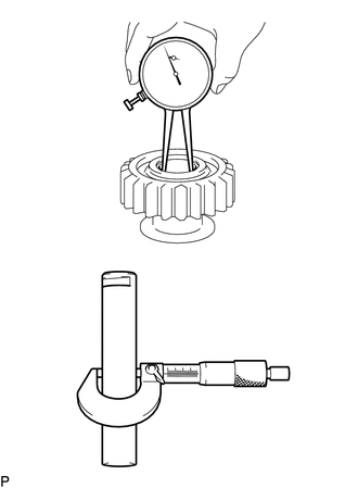
INSPECT COUNTERSHAFT 5TH GEAR RADIAL CLEARANCE
-
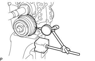
Using a dial indicator, measure the radial clearance.
Standard clearance 0.015 to 0.068 mm (0.000591 to 0.00267 in.) If the clearance is not as specified, replace the counter 5th gear bearing.
-
-
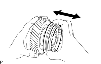
INSPECT NO. 2 SYNCHRONIZER RING
-
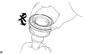
Apply gear oil to the cone of the input shaft, and check that it does not turn in either direction while pushing the No. 2 synchronizer ring.
If it can turn, replace the No. 2 synchronizer ring.
-
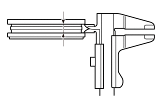
Push the No. 2 synchronizer ring against the cone of the input shaft. Measure the clearance between the No. 2 synchronizer ring and input shaft.
Standard clearance 0.70 to 1.70 mm (0.0276 to 0.0669 in.) If the clearance is not as specified, replace the No. 2 synchronizer ring.
-
-
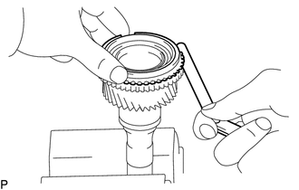
INSPECT NO. 3 SYNCHRONIZER RING
-
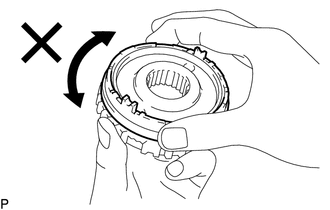
Apply gear oil to the cone part of the No. 5 gear spline piece, and check that it does not turn in either direction while pushing the No. 3 synchronizer ring against the No. 5 gear spline piece.
If it can turn, replace the No. 3 synchronizer ring.
-

Push the No. 3 synchronizer ring against the cone part of the No. 5 gear spline piece. Measure the clearance between the No. 3 synchronizer ring and No. 5 gear spline piece.
Standard clearance 0.68 to 1.32 mm (0.0268 to 0.0519 in.) If the clearance is not as specified, replace the No. 3 synchronizer ring.
-
-
INSPECT NO. 1 GEAR SHIFT FORK
-
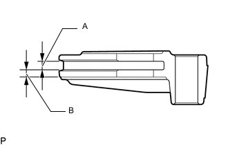
Using a vernier caliper, measure the No. 1 gear shift fork groove A and the thickness B.
Standard groove (A) 5.20 to 5.36 mm (0.205 to 0.211 in.) Maximum groove (A) 5.36 mm (0.211 in.) Standard thickness (B) 4.35 to 4.65 mm (0.172 to 0.183 in.) Minimum thickness (B) 4.35 mm (0.172 in.) If the width is not as specified, replace the No. 1 gear shift fork.
-
-
INSPECT NO. 2 GEAR SHIFT FORK
-
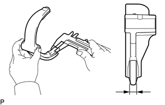
Using a vernier caliper, measure the thickness of the claw part of the No. 2 gear shift fork.
Standard thickness 9.9 to 10.0 mm (0.390 to 0.393 in.) Minimum thickness 9.9 mm (0.390 in.) If the width is not as specified, replace the No. 2 gear shift fork.
-
-
INSPECT NO. 3 GEAR SHIFT FORK
-
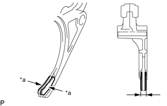
*a Pad Using a vernier caliper, measure the thickness of the claw part of the No. 3 gear shift fork.
Standard thickness 9.76 to 10.24 mm (0.385 to 0.403 in.) Minimum thickness 9.76 mm (0.385 in.) Note
Check the thickness including the pad.
If the measurement result is less than the minimum or the pad is damaged, replace the No. 3 gear shift fork.
-
-
INSPECT NO. 3 TRANSMISSION HUB SLEEVE
-
Check the sliding condition between the countershaft 5th gear and No. 3 transmission hub sleeve.
-
Check the spline gear of the No. 3 transmission hub sleeve for wear.
If there are any defects, replace the No. 3 transmission hub sleeve.
-
Using a vernier caliper, measure the No. 3 transmission hub sleeve groove.
Standard groove 10.5 to 10.6 mm (0.414 to 0.417 in.) Maximum groove 10.6 mm (0.417 in.) If the width is not as specified, replace the No. 3 transmission hub sleeve.
-
-
INSPECT REVERSE IDLER GEAR SUB-ASSEMBLY
-
Using a caliper gauge, measure the inside diameter of the reverse idler gear sub-assembly.
Standard inside diameter 24.040 to 24.061 mm (0.9465 to 0.9472 in.) Maximum inside diameter 24.061 mm (0.9472 in.) If the inside diameter is more than the maximum, replace the reverse idler gear sub-assembly.
-
Using a micrometer, measure the diameter of the sliding part of the reverse idler gear sub-assembly on the reverse idler gear shaft.
Standard diameter 23.979 to 24.000 mm (0.9441 to 0.9448 in.) Minimum diameter 23.979 mm (0.9441 in.) If the diameter is less than the minimum, replace the reverse idler gear shaft.
-
Using a feeler gauge, measure the thrust clearance of the shoe part between the reverse idler gear sub-assembly and reverse shift arm.
Standard clearance 0.05 to 0.35 mm (0.00197 to 0.0137 in.) If the clearance is not as specified, replace the reverse idler gear sub-assembly and reverse shift arm.
-