AIR CONDITIONING SYSTEM TERMINALS OF ECU
-
AIR CONDITIONING AMPLIFIER ASSEMBLY
Figure 1. for 4 Zone Type:
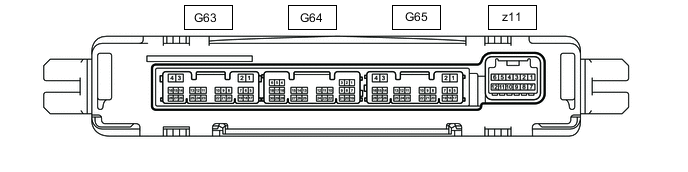
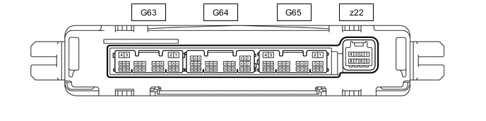
Figure 2. for Dual Type:
-
Disconnect the G63 and G65 air conditioning amplifier assembly connectors.
-
Measure the voltage and resistance according to the value(s) in the table below.
Terminal No.
(Symbol)
Wiring Color Terminal Description Condition Specified Condition G63-4 (+B2) - Body ground LA-B - Body ground Power source (Back-up) Always 11 to 14 V G65-1 (+B1) - Body ground LA-W - Body ground Power source (Back-up) Always 11 to 14 V G65-2 (IG+) - Body ground LA-R - Body ground Power source (IG) Engine switch on (IG) 11 to 14 V Engine switch off Below 1 V G65-4 (GND) - Body ground LA - Body ground Ground Always Below 1 Ω -
Reconnect the G63 and G65 air conditioning amplifier assembly connectors.
-
Measure the voltage and resistance according to the value(s) in the table below.
Terminal No.
(Symbol)
Wiring Color Terminal Description Condition Specified Condition G65-3 (SOL+) - Body ground LA-P - Body ground Compressor solenoid operation signal
-
Engine running
-
Blower switch: LO
-
A/C switch: On
Pulse generation
(See waveform 5)
G65-6 (BLW) - Body ground R - Body ground Blower motor speed control signal
-
Engine switch on (IG)
-
Blower switch: LO
Pulse generation
(See waveform 1)
G65-7 (NANO) - Body ground V - Body ground Ion generator operation signal
-
Engine switch on (IG)
-
Blower switch: Off → LO
4.75 to 5.25 V → Below 1 V G65-11 (CANH) L CAN communication line - - G65-12 (CANL) W CAN communication line - - G65-14 (LIN1) - Body ground B - Body ground LIN communication signal Engine switch on (IG) Pulse generation
(See waveform 2)
G65-16 (LIN3) - Body ground P - Body ground LIN communication signal Engine switch on (IG) Pulse generation
(See waveform 2)
G65-26 (NAIN) - Body ground W - Body ground Ion generator operation condition signal
-
Engine switch on (IG)
-
Blower switch: Off → LO
4.75 to 5.25 V → Below 2.2 V G64-1 (SG-1) - Body ground G - Body ground Ground for sensor Always Below 1 Ω G64-2 (SG-2) - Body ground SB - Body ground Ground for sensor Always Below 1 Ω G64-5 (S5-4) - Body ground GR - Body ground Power source of sensor Engine switch off → on (IG) Below 1 V → 4.75 to 5.25 V G64-6 (S5-3) - Body ground V - Body ground Power source of sensor Engine switch off → on (IG) Below 1 V → 4.75 to 5.25 V G64-9 (MGC) - Body ground*4 R - Body ground Magnetic clutch operation signal
-
Engine running
-
Blower switch: LO
-
A/C switch: Off or on (magnet clutch off)
11 to 14 V
-
Engine running
-
Blower switch: LO
-
A/C switch: On (magnet clutch on)
Below 1 V G64-13 (TAM) - G64-2 (SG-2) B - SB Ambient temperature sensor signal
-
Engine switch on (IG) (do not start the engine and electric motor)
-
Ambient temperature 10°C (50°F)
1.8 to 2.4 V
-
Engine switch on (IG) (do not start the engine and electric motor)
-
Ambient temperature: 15°C (59°F)
1.65 to 2.15 V
-
Engine switch on (IG) (do not start the engine and electric motor)
-
Ambient temperature: 20°C (68°F)
1.5 to 1.95 V
-
Engine switch on (IG) (do not start the engine and electric motor)
-
Ambient temperature: 25°C (77°F)
1.35 to 1.75 V
-
Engine switch on (IG) (do not start the engine and electric motor)
-
Ambient temperature: 30°C (86°F)
1.2 to 1.55 V
-
Engine switch on (IG) (do not start the engine and electric motor)
-
Ambient temperature: 35°C (95°F)
1.0 to 1.4 V
-
Engine switch on (IG) (do not start the engine and electric motor)
-
Ambient temperature: 40°C (104°F)
0.85 to 1.25 V
-
Engine switch on (IG) (do not start the engine and electric motor)
-
Ambient temperature: 45°C (113°F)
0.75 to 1.10 V
-
Engine switch on (IG) (do not start the engine and electric motor)
-
Ambient temperature: 50°C (122°F)
0.65 to 1.0 V G64-14 (TR) - Body ground P - Body ground Room temperature sensor signal
-
Engine switch on (IG)
-
Cabin temperature: 25°C (77°F)
1.8 to 2.2 V
-
Engine switch on (IG)
-
Cabin temperature: 40°C (104°F)
1.2 to 1.6 V G64-20 (ECOS) - Body ground W - Body ground Satellite switch set (ECO drive mode) signal
-
Engine switch on (IG)
-
Satellite switch set (ECO drive mode) off → on
11 to 14 V → Below 1 V G64-21 (LOCK) - Body ground*4 G - Body ground A/C lock sensor signal
-
Engine running
-
Blower switch: LO
-
A/C switch: On
Pulse generation
(See waveform 4)
G64-22 (RRTS) - G64-5 (S5-4) L - GR Cooler thermistor (solar sensor) signal Sensor is subjected to electric light 0.8 to 4.3 V Sensor is covered with a cloth Below 0.8 V G64-24 (PRE) - G63-20 (SG-7) P - G Air conditioner pressure sensor signal
-
Engine running
-
Air conditioning system operating
-
Refrigerant pressure: Normal pressure (below 3025 kPa [30.8 kgf/cm2, 439 psi] and higher than 176 kPa [1.8 kgf/cm2, 26 psi])
0.62 to 4.73 V*1 G64-25 (DGS) - G64-2 (SG-2) R - SB Smog ventilation sensor signal (HC, CO)
-
Engine switch on (IG)
-
Cabin temperature: 20°C (68°F)
-
Humidity: 65%
-
Spray with clean air
5 to 80 kΩ G64-27 (DGS 1) - G64-2 (SG-2) G - SB Smog ventilation sensor signal (NOx)
-
Engine switch on (IG)
-
Cabin temperature: 20°C (68°F)
-
Humidity: 65%
-
Spray with clean air
1.25 to 80 kΩ G63-1 (RGND) - Body ground LA - Body ground Ground Always Below 1 Ω R63-2 (RBUG) - Body ground LA-L - Body ground Ground for BUS IC Always Below 1 Ω G63-3 (RBBU) - R63-2 (RBUG) LA-R - LA-L Power supply for BUS IC Always 11 to 14 V G63-12 (SBLW) - Body ground G - Body ground Rear blower motor speed control signal
-
Engine switch on (IG)
-
Blower switch: LO
Pulse generation
(See waveform 1)
G63-22 (RBUS) - G63-2 (RBUG) V - LA-L BUS IC control signal Engine switch on (IG) Pulse generation
(See waveform 3)
G63-24 (RLIN) - Body ground B - Body ground LIN communication signal Engine switch on (IG) Pulse generation
(See waveform 2)
z11-1 (BUS G) - Body ground*2 - Ground for BUS IC Always Below 1 Ω z11-2 (BUS) - z11-1 (BUS G)*2 - BUS IC control signal Engine switch on (IG) Pulse generation
(See waveform 3)
z11-3 (B BUS) - z11-1 (BUS G)*2 - Power supply for BUS IC Engine switch off 11 to 14 V z11-12 (SGA) - Body ground*2 - Ground for No. 1 cooler thermistor Always Below 1 Ω z11-7 (BUS G) - Body ground*2 - Ground for BUS IC Always Below 1 Ω z11-8 (BUS) - z11-7 (BUS G)*2 - BUS IC control signal Engine switch on (IG) Pulse generation
(See waveform 3)
z11-9 (B BUS) - z11-7 (BUS G)*2 - Power supply for BUS IC Always 11 to 14 V z11-11 (TEA) - z11-12 (SGA)*2 - No. 1 cooler thermistor signal
-
Engine switch on (IG)
-
Evaporator temperature: 0°C (32°F)
1.7 to 2.1 V
-
Engine switch on (IG)
-
Evaporator temperature: 15°C (59°F)
0.9 to 1.3 V z22-2 (BUS G) - Body ground*3 - Ground for BUS IC Always Below 1 Ω z22-3 (BUS) - z22-2 (BUS G)*3 - BUS IC control signal Engine switch on (IG) Pulse generation
(See waveform 3)
z22-4 (B BUS) - z22-2 (BUS G)*3 - Power supply for BUS IC Always 11 to 14 V z22-5 (SGA) - Body ground*3 - Ground for No. 1 cooler thermistor Always Below 1 Ω z22-6 (TEA) - z22-5 (SGA)*3 - No. 1 cooler thermistor signal
-
Engine switch on (IG)
-
Evaporator temperature: 0°C (32°F)
1.7 to 2.1 V -
-
Engine switch on (IG)
-
Evaporator temperature: 15°C (59°F)
0.9 to 1.3 V
-
*1: While sensor voltage is 5 V
-
*2: for 4 Zone Type
-
*3: for Dual Type
-
*4: for 8GR-FKS
-
-
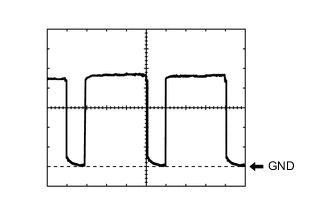
Waveform 1:
Item Content Terminal No. G65-6 (BLW) - Body ground
G63-12 (SBLW) - Body ground
Tool Setting 1 V/DIV., 500 μs./DIV. Vehicle Condition
-
Engine switch on (IG)
-
Blower switch: LO
-
-
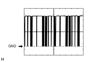
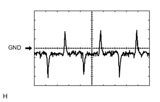
Waveform 2:
Item Content Terminal No. G65-14 (LIN1) - Body ground
G65-16 (LIN3) - Body ground
G63-24 (RLIN) - Body ground
Tool Setting 2 V/DIV., 20 μs./DIV. Vehicle Condition Engine switch on (IG) -
Waveform 3:
Item Content Terminal No. z11-2 (BUS) - z11-1 (BUS G)*1
z11-8 (BUS) - z11-7 (BUS G)*1
G63-22 (RBUS) - G63-2 (RBUG)
z22-3 (BUS) - z22-2 (BUS G)*2
Tool Setting 2 V/DIV., 20 μs./DIV. Vehicle Condition Engine switch on (IG)
-
*1: for 4 Zone Type
-
*2: for Dual Type
-
-
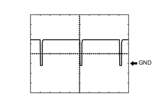
Waveform 4:
Item Content Terminal No. G64-21 (LOCK) - Body ground Tool Setting 200 mV/DIV., 10 ms./DIV. Vehicle Condition
-
Engine running
-
Blower switch: LO
-
A/C switch: On
-
-
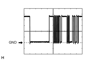
Waveform 5:
Item Content Terminal No. G65-3 (SOL+) - Body ground Tool Setting 5 V/DIV., 500 μs./DIV. Vehicle Condition
-
Engine running
-
Blower switch: LO
-
A/C switch: On
-
-
-
ECM
-
for 8GR-FKS: Click here
-
for V35A-FTS (w/ Canister Pump Module): Click here
-
for V35A-FTS (w/o Canister Pump Module): Click here
-
-
NO. 1 SEMICONDUCTOR POWER INTEGRATION ECU (w/ Heater Accessory)
-
NO. 2 SEMICONDUCTOR POWER INTEGRATION ECU