ENGINE UNIT (for DPF) INSPECTION
-
INSPECT INJECTION GEAR BEARING
-
Check that the bearing is not rough or worn.
If necessary, replace the injection gear.
-
-
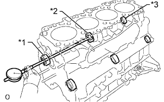
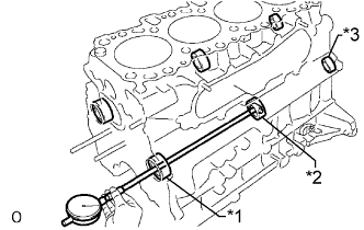
INSPECT NO. 1 IDLE GEAR OIL CLEARANCE
-
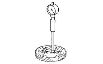
Using a cylinder gauge, measure the inside diameter of the idle gear.
Standard idle gear inside diameter 44.000 to 44.025 mm (1.7323 to 1.7333 in.) -
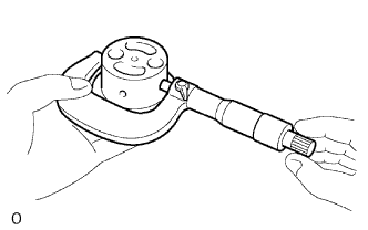
Using a micrometer, measure the diameter of the idle gear shaft.
Standard idle gear shaft diameter 43.955 to 43.990 mm (1.7305 to 1.7319 in.) -
Subtract the idle gear shaft diameter measurement from the idle gear inside diameter measurement.
Standard oil clearance 0.01 to 0.07 mm (0.0004 to 0.0028 in.) Maximum oil clearance 0.20 mm (0.0079 in.) If the oil clearance is more than the maximum, replace the gear and shaft.
-
-
INSPECT INTAKE MANIFOLD
-
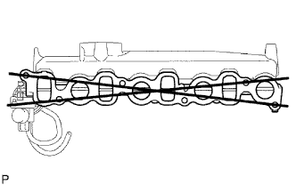
Using a precision straightedge and feeler gauge, measure the warpage of the surface of the intake manifold that contacts the cylinder head.
Maximum warpage 0.4 mm (0.0157 in.) If the warpage is more than the maximum, replace the intake manifold.
-
-
INSPECT EXHAUST MANIFOLD
-
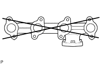
Using a precision straightedge and feeler gauge, measure the warpage of the surface of the exhaust manifold that contacts the cylinder head.
Maximum warpage 0.4 mm (0.0157 in.) If the warpage is more than the maximum, replace the exhaust manifold.
-
-
INSPECT CAMSHAFT
-
Inspect the circle runout.
-
Place the camshaft on V-blocks.
-
Using a dial indicator, measure the circle runout at the center journal.
Maximum circle runout 0.03 mm (0.0012 in.) If the circle runout is more than the maximum, replace the camshaft.
-
-
Inspect the cam lobe height.
-
Using a micrometer, measure the cam lobe height.
Standard cam lobe height 46.99 to 47.09 mm (1.850 to 1.854 in.) Minimum cam lobe height 46.57 mm (1.833 in.) If the cam lobe height is less than the minimum, replace the camshaft.
-
-
Inspect the diameter of the camshaft journal.
-
Using a micrometer, measure the diameter of the camshaft journal for the camshaft bearing.
Standard diameter 27.969 to 27.985 mm (1.1011 to 1.1018 in.) If the diameter is not as specified, check the oil clearance.
-
-
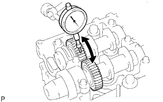
Using a dial indicator, measure the backlash.
-
Install the 2 camshafts.
-
Using a dial indicator, measure the backlash.
Standard backlash 0.035 to 0.089 mm (0.0014 to 0.0035 in.) Maximum backlash 0.189 mm (0.0074 in.) If the backlash is more than the maximum, replace the 2 camshafts.
-
Remove the 2 camshafts.
-
-
-
INSPECT NO. 2 CAMSHAFT
-
Inspect the circle runout.
-
Place the camshaft on V-blocks.
-
Using a dial indicator, measure the circle runout at the center journal.
Maximum circle runout 0.03 mm (0.0012 in.) If the circle runout is more than the maximum, replace the camshaft.
-
-
Inspect the cam lobe height.
-
Using a micrometer, measure the cam lobe height.
Standard cam lobe height 48.31 to 48.41 mm (1.902 to 1.906 in.) Minimum cam lobe height 48.16 mm (1.896 in.) If the cam lobe height is less than the minimum, replace the camshaft.
-
-
Inspect the diameter of the camshaft journal.
-
Using a micrometer, measure the diameter of the camshaft journal for the camshaft bearing.
Standard diameter 27.969 to 27.985 mm (1.1011 to 1.1018 in.) If the diameter is not as specified, check the oil clearance.
-
-
-
INSPECT CAMSHAFT OIL CLEARANCE
-
Clean the bearing caps and journals.
-
Check the bearings for flaking and scoring.
If the bearings are damaged, replace the bearing caps and cylinder head as a set.
-
Place the camshaft on the cylinder head.
-
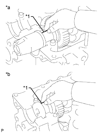
Text in Illustration *1 Plastigage *a Intake Side *b Exhaust Side Lay a strip of Plastigage across each of the journals.
-
Install the bearing caps.
Note
Do not turn the camshaft.
-
Remove the bearing caps.
-
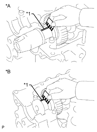
Text in Illustration *1 Plastigage *a Intake Side *b Exhaust Side Measure the Plastigage at its widest point.
Standard oil clearance 0.025 to 0.062 mm (0.0010 to 0.0024 in.) Maximum oil clearance 0.1 mm (0.0039 in.) If the oil clearance is more than the maximum, replace the camshaft. If necessary, replace the bearing caps and cylinder head as a set.
-
Completely remove the Plastigage.
-
Remove the camshaft.
-
-
INSPECT CAMSHAFT THRUST CLEARANCE
-
Install the camshaft.
-
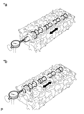
Text in Illustration *a Intake Side *b Exhaust Side Using a dial indicator, measure the thrust clearance while moving the camshaft back and forth.
Standard thrust clearance 0.035 to 0.185 mm (0.0014 to 0.073 in.) Maximum thrust clearance 0.25 mm (0.0098 in.) If the thrust clearance is more than the maximum, replace the camshaft. If necessary, replace the bearing caps and cylinder head as a set.
-
Remove the camshaft.
-
-
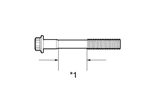
INSPECT CYLINDER HEAD SET BOLT
-
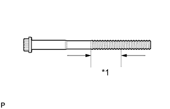
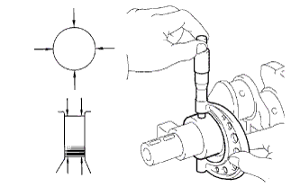
Text in Illustration *1 Measuring Area Using a vernier caliper, measure the diameter of the most elongated threads in the measurement area.
Standard outside diameter 11.8 to 12.0 mm (0.465 to 0.472 in.) Minimum outside diameter 11.6 mm (0.457 in.) Tech Tips
If a visual check reveals no excessively thin areas, check the center of the bolt (see illustration) and find the area that has the smallest diameter.
If the diameter is less than the minimum, replace the cylinder head set bolt.
-
-
INSPECT CYLINDER BLOCK OIL ORIFICE
-
Check the oil orifice for damage or clogging.
If necessary, replace the cylinder block oil orifice.
-
-
INSPECT OIL CHECK VALVE SUB-ASSEMBLY
-
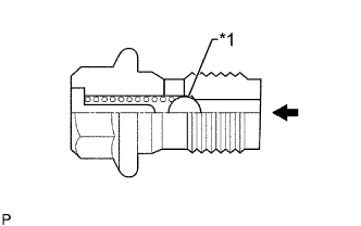
Text in Illustration *1 Ball 
Push Push the ball of the oil check valve with a wooden stick to check if it is stuck.
If the ball of the oil check valve is stuck, replace the oil check valve sub-assembly.
-
-
INSPECT NO. 1 OIL NOZZLE SUB-ASSEMBLY
-
Check the No. 1 oil nozzle for damage or clogging.
If necessary, replace the No. 1 oil nozzle sub-assembly.
-
-
CLEAN CYLINDER BLOCK SUB-ASSEMBLY
-
Using a gasket scraper, remove all the gasket material from the top surface of the cylinder block.
-
Using a soft brush and solvent, thoroughly clean the cylinder block sub-assembly.
-
-
INSPECT CYLINDER BLOCK FOR WARPAGE
-
Inspect for warpage.
-
Using a precision straightedge and feeler gauge, measure the surface of the cylinder block that contacts the cylinder head for warpage.
Maximum warpage 0.1 mm (0.0039 in.) If the warpage is more than the maximum, replace the cylinder block sub-assembly.
-
-
Visually check the cylinders for vertical scratches.
If deep scratches are present, rebore all 4 cylinders. If necessary, replace the cylinder block.
-
-
INSPECT CYLINDER BORE
-
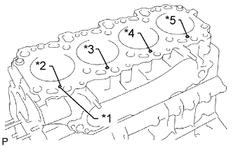
Text in Illustration *1 Mark 1, 2 or 3 *2 No. 1 *3 No. 2 *4 No. 3 *5 No. 4 Inspect the cylinder bore diameter.
Tech Tips
There are 3 standard cylinder bore diameter sizes, marked 1, 2 and 3 accordingly. The mark is stamped on the cylinder block.
-
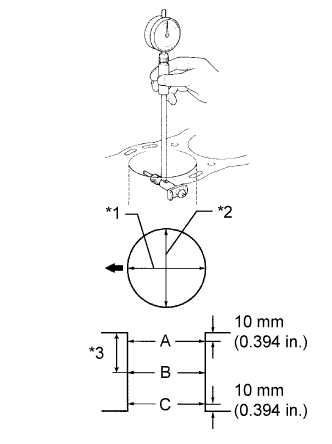
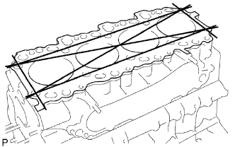
Text in Illustration *1 Axial Direction *2 Thrust Direction *3 Center Front 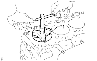
Text in Illustration *1 Ridge Reamer Using a cylinder gauge, measure the cylinder bore diameter at positions A, B and C in the thrust and axial directions.
Standard Diameter Item Specified Condition STD Mark 1 96.00 to 96.01 mm (3.7795 to 3.7799 in.) STD Mark 2 96.01 to 96.02 mm (3.7799 to 3.7803 in.) STD Mark 3 96.02 to 96.03 mm (3.7803 to 3.7807 in.) O/S 0.50 96.50 to 96.53 mm (3.7992 to 3.8004 in.) O/S 0.75 96.75 to 96.78 mm (3.8090 to 3.8102 in.) O/S 1.00 97.00 to 97.03 mm (3.8189 to 3.8201 in.) Maximum Diameter Item Specified Condition STD 96.23 mm (3.7886 in.) O/S 0.50 96.73 mm (3.8083 in.) O/S 0.75 96.98 mm (3.8181 in.) O/S 1.00 97.23 mm (3.8279 in.) If the diameter is more than the maximum, rebore all 4 cylinders. If necessary, replace the cylinder block sub-assembly.
If the wear is less than 0.2 mm (0.0078 in.), using a ridge reamer, grind the top of the cylinder.
-
-
-
CLEAN PISTON
-
Using a groove cleaning tool or broken ring, clean the piston ring grooves.
-
Using solvent and a brush, thoroughly clean the piston.
Note
Do not use a wire brush.
-
-
INSPECT PISTON WITH PIN SUB-ASSEMBLY
Tech Tips
When replacing the piston sub-assembly (w/ pin) with a supply part, there are a number of piston diameter sizes to choose from, but there is only one size of piston pin diameter.
-
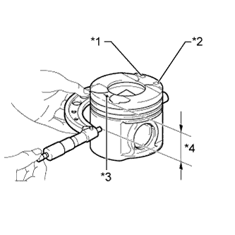
Text in Illustration *1 Size Mark *2 Piston Pin Hole Inside Diameter Mark *3 Front Mark (Arrow) *4 Distance Using a micrometer, measure the piston diameter according to the following conditions: 1) measure at a right angle to the piston center line, and 2) measure at the indicated distance from the piston head.
Distance 63.5 mm (2.50 in.) Standard Piston Diameter Item Specified Condition STD Mark 1 95.92 to 95.93 mm (3.77637 to 3.77676 in.) STD Mark 2 95.93 to 95.94 mm (3.77676 to 3.77715 in.) STD Mark 3 95.94 to 95.95 mm (3.77716 to 3.77755 in.) O/S 0.50 96.42 to 96.45 mm (3.79606 to 3.79723 in.) O/S 0.75 96.67 to 96.70 mm (3.80598 to 3.80707 in.) O/S 1.00 96.92 to 96.95 mm (3.81574 to 3.81692 in.) Standard Pin Hole Inside Diameter Item Specified Condition Mark A 34.011 to 34.015 mm (1.3390 to 1.3392 in.) Mark B 34.015 to 34.019 mm (1.3392 to 1.3393 in.) Mark C 34.019 to 34.023 mm (1.3393 to 1.3395 in.) -
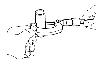
Using a micrometer, measure the piston pin diameter.
Standard Piston Pin Diameter Item Specified Condition Mark A 34.000 to 34.004 mm (1.3386 to 1.3387 in.) Mark B 34.004 to 34.008 mm (1.3387 to 1.3389 in.) Mark C 34.008 to 34.012 mm (1.3389 to 1.3391 in.) -
Subtract the piston pin diameter measurement from the piston pin hole inside diameter measurement.
Standard oil clearance 0.007 to 0.015 mm (0.000276 to 0.000591 in.) If the oil clearance is more than the maximum, replace the piston with pin sub-assembly.
-
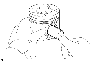
Inspect the piston pin fit.
-
At 80°C (176°F), check that the piston pin can be pushed into the piston pin hole with your thumb.
If the pin can be installed at a lower temperature, replace the piston with pin sub-assembly.
-
-
-
INSPECT PISTON OIL CLEARANCE
-
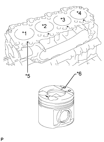
Text in Illustration *1 No. 1 *2 No. 2 *3 No. 3 *4 No. 4 *5 Mark 1, 2 or 3 *6 Size Mark Measure the cylinder bore diameter in the thrust direction.
-
Subtract the piston diameter measurement from the cylinder bore diameter measurement.
Standard oil clearance 0.07 to 0.09 mm (0.0028 to 0.0035 in.) Maximum oil clearance 0.14 mm (0.0055 in.) If the oil clearance is more than the maximum, replace all 4 pistons and rebore all 4 cylinders.
If necessary, replace the cylinder block sub-assembly.
Tech Tips
When the cylinder block is replaced, use a piston with the same number mark as the cylinder diameter marked on a new cylinder block.
-
-
INSPECT RING GROOVE CLEARANCE
-
Using a feeler gauge, measure the clearance between a new piston ring and the wall of the ring groove.
Standard Groove Clearance Item Specified Condition No. 1 piston ring 0.091 to 0.135 mm (0.0036 to 0.0053 in.) No. 2 piston ring 0.090 to 0.135 mm (0.0036 to 0.0053 in.) Oil ring 0.030 to 0.075 mm (0.0012 to 0.0027 in.) If the result is not as specified, replace the piston with pin sub-assembly.
-
-
INSPECT PISTON RING END GAP
-
Insert the piston ring into the cylinder bore.
-
Using a piston, push the piston ring a little beyond the bottom of the ring travel, 120 mm (4.72 in.) from the top of the cylinder block.
-
Using a feeler gauge, measure the end gap.
Standard End Gap Item Specified Condition No. 1 piston ring 0.27 to 0.39 mm (0.0106 to 0.0154 in.) No. 2 piston ring 0.55 to 0.70 mm (0.0217 to 0.0276 in.) Oil ring 0.20 to 0.40 mm (0.0079 to 0.0157 in.) Maximum End Gap Item Specified Condition No. 1 piston ring 0.85 mm (0.0335 in.) No. 2 piston ring 1.07 mm (0.0421 in.) Oil ring 0.77 mm (0.0303 in.) If the end gap is more than the maximum, replace the piston ring.
If the end gap is more than the maximum even with a new piston ring, rebore all 4 cylinders or replace the cylinder block sub-assembly.
-
-
INSPECT PISTON PIN OIL CLEARANCE
-
Text in Illustration *1 Connecting Rod Bush Inside Diameter Mark A, B or C *2 Front Mark Using a caliper gauge, measure the inside diameter of the connecting rod bush.
Standard Bush Inside Diameter Item Specified Condition Mark A 34.012 to 34.016 mm (1.3390 to 1.3392 in.) Mark B 34.016 to 34.020 mm (1.3392 to 1.3394 in.) Mark C 34.020 to 34.024 mm (1.3394 to 1.3395 in.) -
Subtract the piston pin diameter measurement from the bush inside diameter measurement.
Standard oil clearance 0.008 to 0.016 mm (0.0003 to 0.0006 in.) Maximum oil clearance 0.03 mm (0.012 in.) If the oil clearance is more than the maximum, replace the connecting rod sub-assembly.
If necessary, replace the piston with pin sub-assembly.
-
-
INSPECT CONNECTING ROD SUB-ASSEMBLY
-
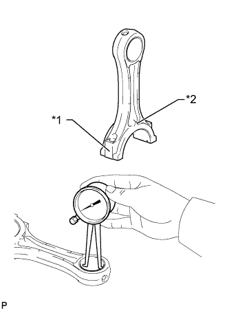
Using a rod aligner and feeler gauge, check the connecting rod alignment.
-

Check if the connecting rod is bent.
Maximum bend 0.03 mm (0.0012 in.) per 100 mm (3.94 in.) If the bend is more than the maximum, replace the connecting rod sub-assembly.
-

Check if the connecting rod is twisted.
Maximum twist 0.15 mm (0.0059 in.) per 100 mm (3.94 in.) If the twist is more than the maximum, replace the connecting rod sub-assembly.
-
-
-
INSPECT CONNECTING ROD BOLT
-
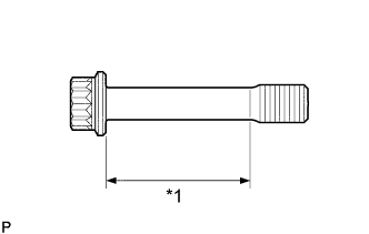
Text in Illustration *1 Tension Portion Using a vernier caliper, measure the diameter of the tension portion of the bolt.
Standard diameter 8.5 to 8.6 mm (0.3346 to 0.3385 in.) Minimum diameter 8.3 mm (0.3268 in.) If the diameter is less than the minimum, replace the connecting rod bolt.
-
-
INSPECT NO. 1 BALANCESHAFT SUB-ASSEMBLY
-
Using a cylinder gauge, measure the inside diameter of the balanceshaft bearing.
Standard Bearing Inside Diameter Item Specified Condition No. 1 42.000 to 42.020 mm (1.6535 to 1.6543 in.) No. 2 41.000 to 41.020 mm (1.6142 to 1.6150 in.) No. 3 32.000 to 32.020 mm (1.2598 to 1.2606 in.) Text in Illustration *1 No. 1 *2 No. 2 *3 No. 3 -
Using a micrometer, measure the outside diameter of the balanceshaft main journals.
Standard Main Journal Diameter Item Specified Condition No. 1 41.941 to 41.960 mm (1.6512 to 1.6520 in.) No. 2 40.931 to 40.950 mm (1.6115 to 1.6122 in.) No. 3 31.941 to 31.960 mm (1.2575 to 1.2583 in.) -
Subtract the outside diameter of the balanceshaft main journal from the inside diameter of the balanceshaft bearing.
Standard Oil Clearance Item Specified Condition No. 1 0.040 to 0.079 mm (0.0016 to 0.0031 in.) No. 2 0.050 to 0.089 mm (0.0020 to 0.0035 in.) No. 3 0.040 to 0.079 mm (0.0016 to 0.0031 in.) Maximum Oil Clearance Item Specified Condition No. 1 0.18 mm (0.0071 in.) No. 2 0.19 mm (0.0075 in.) No. 3 0.18 mm (0.0071 in.) If the clearance is more than the maximum, replace the cylinder block sub-assembly and No. 1 balanceshaft sub-assembly.
-
-
INSPECT NO. 2 BALANCESHAFT SUB-ASSEMBLY
-
Text in Illustration *1 No. 1 *2 No. 2 *3 No. 3 Using a cylinder gauge, measure the inside diameter of the balanceshaft bearing.
Standard Bearing Inside Diameter Item Specified Condition No. 1 42.000 to 42.020 mm (1.6535 to 1.6543 in.) No. 2 41.000 to 41.020 mm (1.6142 to 1.6150 in.) No. 3 32.000 to 32.020 mm (1.2598 to 1.2606 in.) -
Using a micrometer, measure the outside diameter of the balanceshaft main journals.
Standard Main Journal Diameter Item Specified Condition No. 1 41.941 to 41.960 mm (1.6512 to 1.6520 in.) No. 2 40.931 to 40.950 mm (1.6115 to 1.6122 in.) No. 3 31.941 to 31.960 mm (1.2575 to 1.2583 in.) -
Subtract the outside diameter of the balanceshaft main journal from the inside diameter of the balanceshaft bearing.
Standard Oil Clearance Item Specified Condition No. 1 0.040 to 0.079 mm (0.0016 to 0.0031 in.) No. 2 0.050 to 0.089 mm (0.0020 to 0.0035 in.) No. 3 0.040 to 0.079 mm (0.0016 to 0.0031 in.) Maximum Oil Clearance Item Specified Condition No. 1 0.18 mm (0.0071 in.) No. 2 0.19 mm (0.0075 in.) No. 3 0.18 mm (0.0071 in.) If the clearance is more than the maximum, replace the cylinder block sub-assembly and No. 2 balanceshaft sub-assembly.
-
-
INSPECT CRANKSHAFT
-
Inspect for circle runout.
-
Place the crankshaft on V-blocks.
-
Using a dial indicator, measure the circle runout at the center journal.
Maximum circle runout 0.03 mm (0.0012 in.) If the circle runout is more than the maximum, replace the crankshaft.
-
-
Inspect the main journals and crank pins.
-
Using a micrometer, measure the diameter of each main journal and crank pin.
Standard Main Journal Diameter Item Specified Condition Mark 1 69.994 to 70.000 mm (2.75566 to 2.75590 in.) Mark 2 69.988 to 69.994 mm (2.75543 to 2.75566 in.) Mark 3 69.982 to 69.988 mm (2.75519 to 2.75543 in.) U/S 0.25 69.745 to 69.755 mm (2.7459 to 2.7463 in.) U/S 0.50 69.495 to 69.505 mm (2.7360 to 2.7364 in.) Standard Crank Pin Diameter Item Specified Condition Mark 1 58.994 to 59.000 mm (2.32259 to 2.32283 in.) Mark 2 58.988 to 58.994 mm (2.32236 to 2.32259 in.) Mark 3 58.982 to 58.988 mm (2.32212 to 2.32239 in.) U/S 0.25 58.745 to 58.755 mm (2.3128 to 2.3132 in.) U/S 0.50 58.495 to 58.505 mm (2.3029 to 2.3033 in.) If the diameter is not as specified, check the connecting rod oil clearance Click here and crankshaft oil clearance Click here. If necessary, grind or replace the crankshaft.
-
Check each main journal and crank pin for taper and out-of-round as shown in the illustration.
Maximum taper and out-of-round 0.02 mm (0.0008 in.) If the taper and out-of-round is more than the maximum, replace the crankshaft.
-
-
If necessary, grind and hone the main journals and/or crank pins.
-
Grind and hone the main journals and/or crank pins to the finished undersized diameter (refer to the procedures above).
-
Install new main journal and/or crank pin undersized bearings.
-
-
-
INSPECT CRANKSHAFT BEARING CAP SET BOLT
-
Text in Illustration *1 Measuring Area Using a vernier caliper, measure the diameter of the crankshaft bearing cap set bolt in the measuring area.
Standard diameter 13.5 to 14.0 mm (0.5351 to 0.5512 in.) Minimum diameter 12.6 mm (0.4961 in.) If the diameter is less than the minimum, replace the crankshaft bearing cap set bolt.
-