DYNAMIC TORQUE CONTROL 4WD/AWD SYSTEM TC and CG Terminal Circuit
| DTC Code | DTC Name |
|---|---|
| TC and CG Terminal Circuit |
DESCRIPTION
for Segment Display Type:
Connecting terminals TC and CG of the DLC3 causes the 4WD ECU assembly to display 2-digit DTCs by flashing the 4WD/AWD warning light.
for Dot Display Type:
Connecting terminals TC and CG of the DLC3 causes the 4WD ECU assembly to display a DTC on the multi-information display.
When each warning light remains blinking, a short to ground in the wiring of terminal TC of the DLC3 or an internal short to ground in each ECU is suspected.
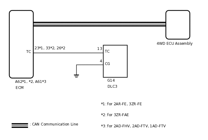
WIRING DIAGRAM
CAUTION / NOTICE / HINT
PROCEDURE
CHECK FOR DTC (CAN COMMUNICATION SYSTEM)
Check if the CAN communication system DTC is output.
for LHD:Click here
for RHD:Click here
Result
Proceed to
CAN communication system DTC is not output
CAN communication system DTC is output (for LHD)
CAN communication system DTC is output (for RHD)
CAN communication system DTC is output (for LHD) GO TO CAN COMMUNICATION SYSTEM (HOW TO PROCEED WITH TROUBLESHOOTING)
CAN communication system DTC is output (for RHD) GO TO CAN COMMUNICATION SYSTEM (HOW TO PROCEED WITH TROUBLESHOOTING)
INSPECT DLC3
-
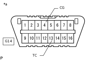
*a
Front view of DLC3
Turn the ignition switch to ON.
Measure the voltage according to the value(s) in the table below.
Standard Voltage
Tester Connection
Switch Condition
Specified Condition
G14-13 (TC) - G14-4 (CG)
Ignition switch ON
11 to 14 V
Result
Proceed to
OK
NG
OK INSPECT ECM (TC of DLC3 INPUT)Click here
-
CHECK HARNESS AND CONNECTOR (TC OF DLC3 - TC OF ECM AND BODY GROUND)
Turn the ignition switch off.
for 2AR-FE, 3ZR-FAE, 3ZR-FE:
Disconnect the A62 ECM connector.
for 2AD-FHV, 2AD-FTV, 1AD-FTV:
Disconnect the A61 ECM connector.
Measure the resistance according to the value(s) in the table below.
Standard Resistance
Table 1. for 2AR-FE, 3ZR-FE Tester Connection
Condition
Specified Condition
G14-13 (TC) - A62-23 (TC)
Always
Below 1 Ω
G14-13 (TC) - Body ground
Always
10 kΩ or higher
Table 2. for 2AD-FHV, 2AD-FTV, 1AD-FTV Tester Connection
Condition
Specified Condition
G14-13 (TC) - A61-26 (TC)
Always
Below 1 Ω
G14-13 (TC) - Body ground
Always
10 kΩ or higher
Table 3. for 3ZR-FAE Tester Connection
Condition
Specified Condition
G14-13 (TC) - A62-33 (TC)
Always
Below 1 Ω
G14-13 (TC) - Body ground
Always
10 kΩ or higher
Result
Proceed to
OK
NG
NG REPAIR OR REPLACE HARNESS OR CONNECTOR
CHECK HARNESS AND CONNECTOR (CG OF DLC3 - BODY GROUND)
-
*a
Front view of DLC3
Measure the resistance according to the value(s) in the table below.
Standard Resistance
Tester Connection
Condition
Specified Condition
G14-4 (CG) - Body ground
Always
Below 1 Ω
Result
Proceed to
OK
NG
NG REPAIR OR REPLACE HARNESS OR CONNECTOR
-
INSPECT ECM (TC of DLC3 INPUT)
-
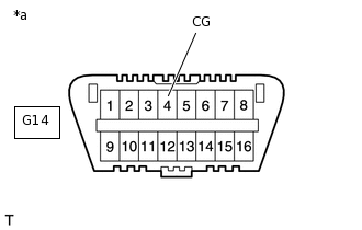
*a
Front view of DLC3
Turn the ignition switch off.
Using SST, connect terminals 13 (TC) and 4 (CG) of the DLC3.
Turn the ignition switch to ON.
Check that the malfunction indicator lamp is blinking.
09843-18040
Result
Proceed to
Malfunction indicator lamp is blinking (for 2AD-FHV)
Malfunction indicator lamp is blinking (for 2AD-FTV)
Malfunction indicator lamp is blinking (for 2AR-FE)
Malfunction indicator lamp is blinking (for 3ZR-FAE)
Malfunction indicator lamp is blinking (for 3ZR-FE)
Malfunction indicator lamp is blinking (for 1AD-FTV)
Malfunction indicator lamp is not blinking
-