ENGINE UNIT DISASSEMBLY
PROCEDURE
REMOVE OIL FILLER CAP SUB-ASSEMBLY
-
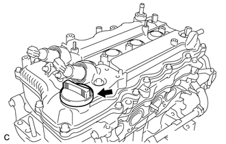
Remove the oil filler cap sub-assembly from the cylinder head cover sub-assembly.
-
REMOVE OIL FILLER CAP GASKET
-
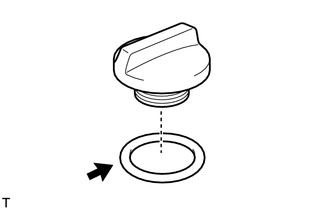
Remove the oil filler cap gasket from the oil filler cap sub-assembly.
-
REMOVE SPARK PLUG
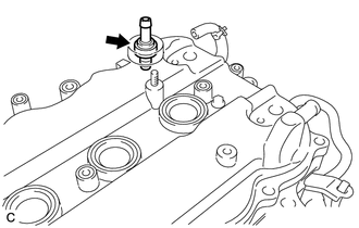
REMOVE NO. 1 CRANK POSITION SENSOR
-
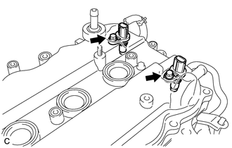
Remove the 2 bolts and 2 No. 1 crank position sensors from the cylinder head cover sub-assembly.
-
REMOVE CAMSHAFT TIMING OIL CONTROL VALVE ASSEMBLY
-
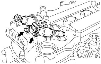
Remove the 2 bolts and 2 camshaft timing oil control valve assemblies from the cylinder head cover sub-assembly.
Remove the 2 O-rings from the 2 camshaft timing oil control valve assemblies.
-
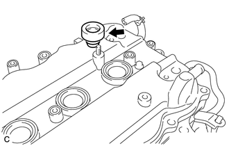
REMOVE VENTILATION VALVE SUB-ASSEMBLY
-
Remove the ventilation valve sub-assembly from the cylinder head cover sub-assembly.
-
REMOVE VENTILATION SYSTEM GROMMET
-
Remove the ventilation system grommet from the cylinder head cover sub-assembly.
-
REMOVE REAR ENGINE OIL SEAL (w/o Stop and Start System)
REMOVE REAR ENGINE OIL SEAL (w/ Stop and Start System)
REMOVE CRANKSHAFT BEARING (w/ Stop and Start System)
-
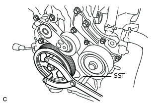
Using SST, hold the crankshaft.
09960-10010
09962-01000
09963-01000
-
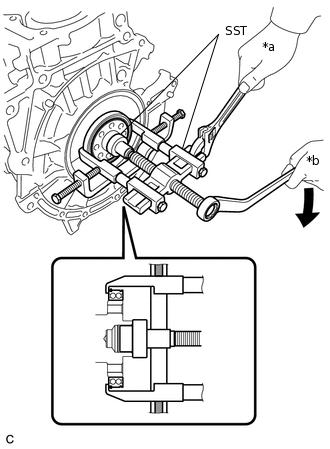
*a
Hold
*b
Turn
Using SST, remove the crankshaft bearing from the crankshaft.
09950-40011
09951-04010
09952-04010
09953-04020
09954-04010
09955-04071
09957-04010
09958-04011
09950-60010
09951-00280
09951-00380
09952-06010
Remove the snap ring from the crankshaft bearing.
-
REMOVE CYLINDER HEAD COVER SUB-ASSEMBLY
Tip: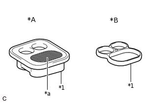
*A
w/ Mesh Type
*B
w/o Mesh Type
*1
Camshaft Bearing Cap Oil Hole Gasket
*a
Mesh
There are 2 types of camshaft bearing cap oil hole gaskets: with mesh and without mesh. For the without mesh type, the oil control valve filter is installed to the camshaft bearing cap.
-
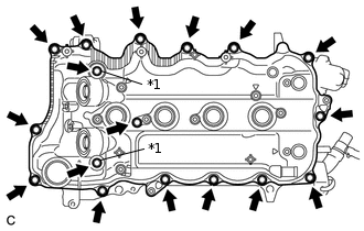
*1
Seal Washer
Remove the 17 bolts, 2 seal washers and cylinder head cover sub-assembly.
Note:Be careful not to drop any of the gaskets into the engine when removing the cylinder head cover sub-assembly because the gaskets may stick to the cylinder head cover sub-assembly.
-
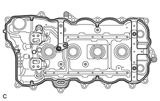
Remove the cylinder head cover gasket from the cylinder head cover sub-assembly.
-
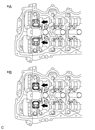
*A
w/ Mesh Type
*B
w/o Mesh Type
Remove the 2 camshaft bearing cap oil hole gaskets from the camshaft bearing cap.
Note:If any camshaft bearing cap oil hole gasket is missing, check that no camshaft bearing cap oil hole gaskets are stuck to the cylinder head cover sub-assembly.
-
REMOVE CRANK POSITION SENSOR
-
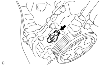
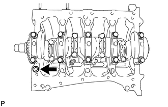
Remove the bolt and crank position sensor.
-
REMOVE ENGINE OIL PRESSURE SWITCH ASSEMBLY
-
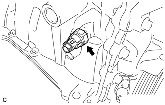
Using a 24 mm deep socket wrench, remove the engine oil pressure switch assembly from the cylinder block sub-assembly.
-
REMOVE KNOCK CONTROL SENSOR
-
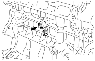
Remove the bolt and knock control sensor from the cylinder block sub-assembly.
-
REMOVE ENGINE COOLANT TEMPERATURE SENSOR
-
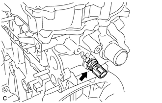
Using a 19 mm deep socket wrench, remove the engine coolant temperature sensor from the cylinder head sub-assembly.
Remove the gasket from the engine coolant temperature sensor.
-
REMOVE OIL FILTER ELEMENT
REMOVE WATER INLET
REMOVE NO. 2 WATER INLET HOUSING GASKET
REMOVE THERMOSTAT
SET NO. 1 CYLINDER TO TDC/COMPRESSION
Turn the crankshaft until its groove and the groove of the timing chain cover sub-assembly are aligned.
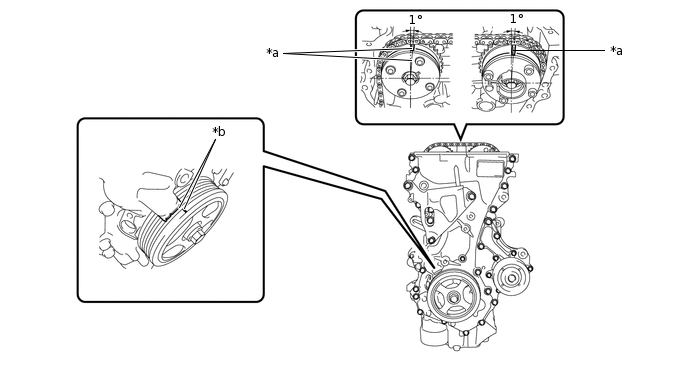
*a
Timing Mark
*b
Groove
Check that each timing mark of the camshaft timing gear assembly and camshaft timing exhaust gear assembly are positioned as shown in the illustration. If not, turn the crankshaft 1 revolution (360°) to align the timing marks as shown in the illustration.
REMOVE CRANKSHAFT PULLEY
REMOVE TIMING CHAIN COVER SUB-ASSEMBLY
-
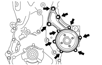
Remove the 9 bolts and engine water pump assembly and gasket from the timing chain cover sub-assembly.
-
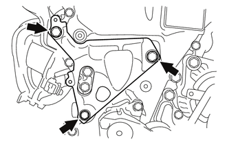
Remove the 3 bolts and engine mounting bracket RH.
-
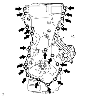
*1
Seal Washer
Remove the 21 bolts and seal washer.
-
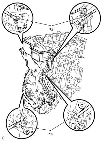
*a
Protective Tape
Remove the timing chain cover sub-assembly by prying between the timing chain cover sub-assembly and cylinder head sub-assembly or cylinder block sub-assembly with a screwdriver.
Note:Be careful not to damage the contact surfaces of the timing chain cover sub-assembly, cylinder block sub-assembly, and cylinder head sub-assembly.
Tip:Tape the screwdriver tip before use.
-
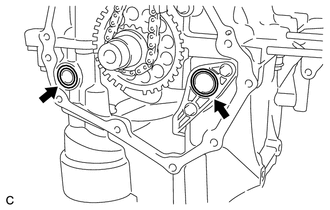
Remove the 2 O-rings from the oil pan sub-assembly and oil strainer sub-assembly.
-
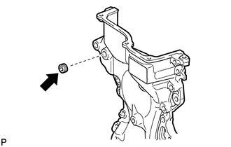
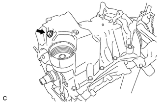
Using an 8 mm socket hexagon wrench, remove the plug from the timing chain cover sub-assembly.
-
REMOVE TIMING CHAIN COVER OIL SEAL
REMOVE NO. 1 CHAIN TENSIONER ASSEMBLY
REMOVE NO. 2 CHAIN VIBRATION DAMPER
REMOVE TIMING CHAIN TENSION ARM
REMOVE CHAIN SUB-ASSEMBLY
REMOVE TIMING CHAIN GUIDE
REMOVE CAMSHAFT TIMING GEAR ASSEMBLY
Check the lock of the camshaft timing gear assembly.
Release the lock pin.
Note:Before removing the camshaft timing gear assembly, make sure that the lock pin has been released.
-
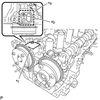
*a
Adhesive Tape Sealing Area
*b
Prick a Hole
*c
Adhesive Tape
Clean the VVT oil hole on the intake side of the camshaft bearing cap, and completely seal the oil hole with adhesive tape or equivalent as shown in the illustration to prevent air from leaking.
Note:Be sure to seal the oil hole completely because air leaks due to insufficient sealing will prevent the lock pin from being released.
Prick a hole in the adhesive tape sealing the oil hole as shown in the illustration. (Procedure A)
-
Apply approximately 150 kPa (1.5 kgf/cm2, 22 psi) of air pressure to the hole pricked in procedure A to release the lock pin.
Note:If air leaks out, reattach adhesive tape.
Cover the oil hole with a piece of cloth when applying air pressure to prevent oil from spraying.
Do not lock the camshaft timing gear assembly. If it is locked, release the lock pin again.
Tip:The camshaft timing gear assembly may be turned in the advance direction without applying any force.
If enough air pressure cannot be applied because of air leakage from the port, releasing the lock pin may be difficult.
Remove the adhesive tape from the camshaft bearing cap.
-
-
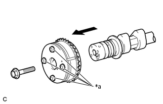
*a
Do not Remove
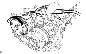
Remove the bolt while holding the hexagonal portion of the camshaft, then remove the camshaft timing gear assembly.
Note:Before removing the camshaft timing gear assembly, make sure that the lock pin has been released.
Be sure not to remove the other 4 bolts.
Keep the camshaft timing gear assembly horizontal while removing it from the camshaft.
REMOVE CAMSHAFT TIMING EXHAUST GEAR ASSEMBLY
-
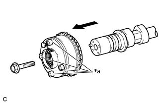
*a
Do Not Remove
Remove the bolt while holding the hexagonal portion of the No. 2 camshaft, then remove the camshaft timing exhaust gear assembly.
Note:Be sure not to remove the other 4 bolts.
Keep the camshaft timing exhaust gear assembly horizontal while removing it from the No. 2 camshaft.
-
REMOVE CAMSHAFT BEARING CAP
REMOVE OIL CONTROL VALVE FILTER
Tip:
*A
w/ Mesh Type
*B
w/o Mesh Type
*1
Camshaft Bearing Cap Oil Hole Gasket
*a
Mesh
There are 2 types of camshaft bearing cap oil hole gaskets: with mesh and without mesh. For the without mesh type, the oil control valve filter is installed to the camshaft bearing cap.
-
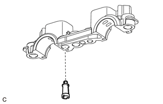
Remove the oil control valve filter from the camshaft bearing cap.
-
REMOVE NO. 2 CAMSHAFT
REMOVE CAMSHAFT
REMOVE NO. 1 VALVE ROCKER ARM SUB-ASSEMBLY
Tip: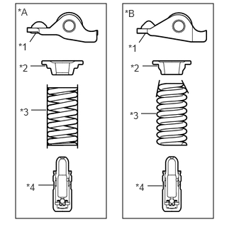
*A
Type A
*B
Type B
*1
No. 1 Valve Rocker Arm Sub-assembly
*2
Valve Spring Retainer
*3
Compression Spring
*4
Valve Lash Adjuster Assembly
Type A and Type B can be distinguished by the shape of the compression spring.
Type
Compression Spring Shape
A
Straight
B
Taper
Type A and Type B:
-
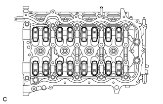
Remove the 16 No. 1 valve rocker arm sub-assemblies.
Tip:Arrange the removed parts in the correct order.
-
REMOVE VALVE LASH ADJUSTER ASSEMBLY
Tip:
*A
Type A
*B
Type B
*1
No. 1 Valve Rocker Arm Sub-assembly
*2
Valve Spring Retainer
*3
Compression Spring
*4
Valve Lash Adjuster Assembly
Type A and Type B can be distinguished by the shape of the compression spring.
Type
Compression Spring Shape
A
Straight
B
Taper
Type A and Type B:
-
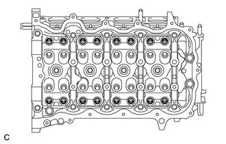
Remove the 16 valve lash adjuster assemblies from the cylinder head sub-assembly.
Tip:Arrange the removed parts in the correct order.
-
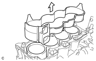
REMOVE CAMSHAFT HOUSING SUB-ASSEMBLY
REMOVE CYLINDER HEAD SUB-ASSEMBLY
REMOVE CYLINDER HEAD GASKET
REMOVE CYLINDER BLOCK WATER JACKET SPACER
-
Remove the cylinder block water jacket spacer from the cylinder block sub-assembly.
-
REMOVE OIL PAN DRAIN PLUG
-
Remove the oil pan drain plug and gasket from the oil pan sub-assembly.
-
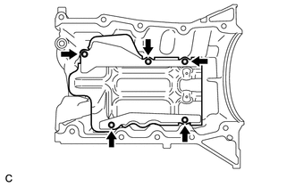
REMOVE OIL PAN SUB-ASSEMBLY
-
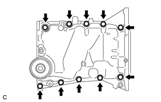
Uniformly loosen and remove the 10 bolts.
-
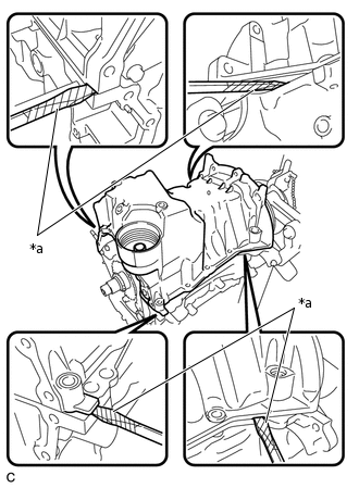
*a
Protective Tape
Using a screwdriver, remove the oil pan sub-assembly by prying between the oil pan sub-assembly and cylinder block sub-assembly.
Note:Be careful not to damage the contact surfaces of the oil pan sub-assembly and cylinder block sub-assembly.
Tip:Tape the screwdriver tip before use.
-
Remove the gasket from the cylinder block sub-assembly.
-
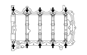
REMOVE NO. 1 OIL PAN BAFFLE PLATE
-
Remove the 5 bolts and No. 1 oil pan baffle plate from the oil pan sub-assembly.
-
REMOVE OIL STRAINER SUB-ASSEMBLY
-
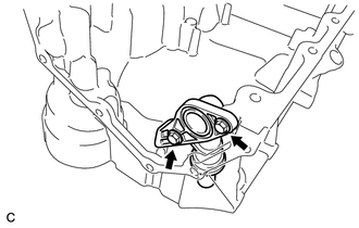
Remove the 2 bolts and oil strainer sub-assembly from the oil pan sub-assembly.
-
REMOVE RING PIN
Note:It is not necessary to remove the ring pins unless they are being replaced.
-
Remove the 10 ring pins from the camshaft housing sub-assembly.
-
REMOVE STRAIGHT PIN
Note:It is not necessary to remove the straight pins unless they are being replaced.
-
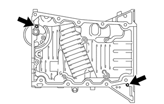
Remove the 2 straight pins from the oil pan sub-assembly.
-