CHARGING SYSTEM, Diagnostic DTC:P1550,P1551 and P1552
| DTC Code | DTC Name |
|---|---|
| P1550 | Battery Current Sensor Circuit |
| P1551 | Battery Current Sensor Circuit Low |
| P1552 | Battery Current Sensor Circuit High |
DESCRIPTION
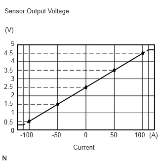
The battery current sensor assembly installed on the negative (-) battery terminal detects the amount of current supplied from the generator.
The battery current sensor assembly changes current to voltage (at the negative (-) battery terminal) and sends it to the ECM. The ECM controls the voltage of the generator based on the signals from the battery current sensor assembly.
DTC No. |
Detection Item |
DTC Detection Condition |
Trouble Area |
Warning Indicate |
Memory |
Note |
|---|---|---|---|---|---|---|
P1550 |
Battery Current Sensor Circuit |
Difference between the maximum and minimum current values of the battery current sensor is less than 1 A for 10 seconds or more with the ignition switch ON (1 trip detection logic) |
|
Charge warning light does not come on |
DTC stored |
w/ Battery Current Sensor |
P1551 |
Battery Current Sensor Circuit Low |
Battery current sensor output value is less than 0.2 V for 0.5 seconds or more with the ignition switch ON (1 trip detection logic) |
|
Charge warning light does not come on |
DTC stored |
w/ Battery Current Sensor |
P1552 |
Battery Current Sensor Circuit High |
Battery current sensor output value is higher than 4.8 V for 0.5 seconds or more with the ignition switch ON (1 trip detection logic) |
|
Charge warning light does not come on |
DTC stored |
w/ Battery Current Sensor |
WIRING DIAGRAM
Refer to DTC P0516.
CAUTION / NOTICE / HINT
Before replacing the ECM, refer to Service Bulletin.
PROCEDURE
CHECK ANY OTHER DTCS OUTPUT (IN ADDITION TO DTC P1550, P1551 OR P1552)
Connect the GTS to the DLC3.
Turn the ignition switch to ON.
Turn the GTS on.
Enter the following menus: Powertrain / Engine and ECT / Trouble Codes.
Read the DTCs.
Powertrain > Engine and ECT > Trouble Codes
Result
Result
Proceed to
DTC P1550, P1551 or P1552 is output.
A
DTC P1550, P1551 or P1552 and other DTCs are output.
B
Tip:If any DTCs other than P1550, P1551 or P1552 are output, troubleshoot those DTCs first.
READ VALUE USING GTS (BATTERY CURRENT)
Turn all of the electrical systems (headlights, blower motor, rear defogger, etc.) off.
Connect the GTS to the DLC3.
Turn the ignition switch to ON.
Turn the GTS on.
Enter the following menus: Powertrain / Engine and ECT / Data List / Battery Current.
According to the display on the GTS, read the Data List.
Powertrain > Engine and ECT
Tester Display
Measurement Item
Range
Normal Condition
Diagnostic Note
Battery Current
Battery current
Min.: -125 A, Max.: 124.9 A
Changes according to alternator output:
While driving after engine warmed up
If the result is not as specified, a malfunction of the charging control system is suspected.
Powertrain > Engine and ECT > Data List
Tester Display
Battery Current
Result
Result
Proceed to
Battery current is maintained at 0 A, or fluctuates by +/- 1 A or less between -100 and 100 A.
A
Battery current fluctuates between -20 and 0 A.
B
B CHECK FOR INTERMITTENT PROBLEMS
INSPECT BATTERY CURRENT SENSOR ASSEMBLY
Inspect the battery current sensor assembly.
Result
Result
Proceed to
OK (for Sedan)
A
OK (except Sedan)
B
NG
C
B CHECK HARNESS AND CONNECTOR (ECM - BATTERY CURRENT SENSOR ASSEMBLY)Click here
CHECK HARNESS AND CONNECTOR (ECM - BATTERY CURRENT SENSOR ASSEMBLY)
Disconnect the B186 ECM connector.
Disconnect the B232 battery current sensor assembly connector.
Measure the resistance according to the value(s) in the table below.
Standard Resistance (Check for Open)
Tester Connection
Condition
Specified Condition
B186-87 (THB) - B232-1 (THB)
Always
Below 1 Ω
B186-118 (EIB) - B232-4 (E2)
Always
Below 1 Ω
B186-117 (VCIB) - B232-2 (VC5)
Always
Below 1 Ω
Standard Resistance (Check for Short)
Tester Connection
Condition
Specified Condition
B186-87 (THB) or B232-1 (THB) - Body ground
Always
10 kΩ or higher
B186-118 (EIB) or B232-4 (E2) - Body ground
Always
10 kΩ or higher
B186-117 (VCIB) or B232-2 (VC5) - Body ground
Always
10 kΩ or higher
Result
Proceed to
OK
NG
NG REPAIR OR REPLACE HARNESS OR CONNECTOR
CHECK HARNESS AND CONNECTOR (ECM - BATTERY CURRENT SENSOR ASSEMBLY)
Disconnect the B186 ECM connector.
Disconnect the A164 battery current sensor assembly connector.
Measure the resistance according to the value(s) in the table below.
Standard Resistance (Check for Open)
Tester Connection
Condition
Specified Condition
B186-87 (THB) - A164-1 (THB)
Always
Below 1 Ω
B186-118 (EIB) - A164-4 (E2)
Always
Below 1 Ω
B186-117 (VCIB) - A164-2 (VC5)
Always
Below 1 Ω
Standard Resistance (Check for Short)
Tester Connection
Condition
Specified Condition
B186-87 (THB) or A164-1 (THB) - Body ground
Always
10 kΩ or higher
B186-118 (EIB) or A164-4 (E2) - Body ground
Always
10 kΩ or higher
B186-117 (VCIB) or A164-2 (VC5) - Body ground
Always
10 kΩ or higher
Result
Proceed to
OK
NG
NG REPAIR OR REPLACE HARNESS OR CONNECTOR