CRUISE CONTROL SYSTEM TERMINALS OF ECM
-
CHECK ECM (for 1KD-FTV)

-
Disconnect the B72 and D98 ECM connectors.
-
Measure the voltage and resistance according to the value(s) in the table below.
Terminal No. (Symbol) Wiring Color Terminal Description Condition Specified Condition B72-2 (BATT) - Body ground W - Body ground Power source circuit Always 11 to 14 V B72-25 (IGSW) - Body ground B - Body ground IG power source circuit Ignition switch ON 11 to 14 V Ignition switch off Below 1 V B72-34 (ST1-) - Body ground R - Body ground Stop light switch signal circuit Ignition switch ON, brake pedal released 11 to 14 V Ignition switch ON, brake pedal depressed Below 1 V B72-35 (STP) - Body ground Y - Body ground Stop light switch signal circuit Brake pedal depressed 11 to 14 V Brake pedal released Below 1 V B72-23 (CCS) - Body ground SB - Body ground Cruise control switch circuit Cruise control main switch on Below 2.5 Ω Cruise control main switch off 1 MΩ or higher +RES switch held on 235 to 245 Ω -SET switch held on 620 to 640 Ω CANCEL switch held on 1510 to 1570 Ω D98-73 (CLSW) - Body ground* R - Body ground Clutch switch signal circuit Ignition switch ON, clutch pedal depressed 11 to 14 V Ignition switch ON, clutch pedal released Below 1 V D98-109 (E1) - Body ground W-B - Body ground Ground Always Below 1 Ω *: for Manual Transmission
If the result is not as specified, there may be a malfunction on the wire harness side.
-
-
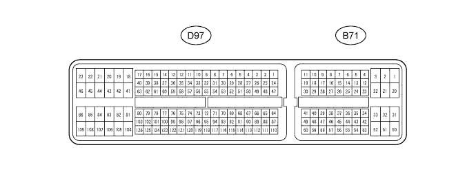
CHECK ECM (for 2TR-FE)
-
Disconnect the B71 and D97 ECM connectors.
-
Measure the voltage and resistance according to the value(s) in the table below.
Terminal No. (Symbol) Wiring Color Terminal Description Condition Specified Condition B71-20 (BATT) - Body ground W - Body ground Power source circuit Always 11 to 14 V B71-27 (IGSW) - Body ground B - Body ground IG power source circuit Ignition switch ON 11 to 14 V Ignition switch off Below 1 V B71-35 (ST1-) - Body ground R - Body ground Stop light switch signal circuit Ignition switch ON, brake pedal released 11 to 14 V Ignition switch ON, brake pedal depressed Below 1 V B71-36 (STP) - Body ground Y - Body ground Stop light switch signal circuit Brake pedal depressed 11 to 14 V Brake pedal released Below 1 V B71-40 (CCS) - Body ground SB - Body ground Cruise control switch circuit Cruise control main switch on Below 2.5 Ω Cruise control main switch off 1 MΩ or higher +RES switch held on 235 to 245 Ω -SET switch held on 620 to 640 Ω CANCEL switch held on 1510 to 1570 Ω B71-47 (D) - Body ground* R - Body ground Clutch switch signal circuit Ignition switch ON, clutch pedal depressed 11 to 14 V Ignition switch ON, clutch pedal released Below 1 V B71-32 (EC) - Body ground W-B - Body ground Ground Always Below 1 Ω D97-105 (E1) - Body ground W-B - Body ground *: for Manual Transmission
If the result is not as specified, there may be a malfunction on the wire harness side.
-