FRONT DOOR LOCK INSPECTION
PROCEDURE
-
INSPECT FRONT DOOR LOCK ASSEMBLY LH (w/o Double Locking System)
-
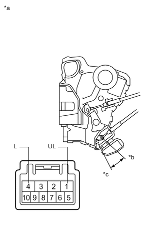
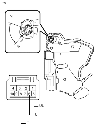
Text in Illustration *a Component without harness connected
(Front Door Lock Assembly LH)
*b Unlock *c Lock Check the operation of the door lock motor.
-
Apply auxiliary battery voltage and check the operation of the door lock motor.
OK Connection Result Auxiliary battery positive (+) → Terminal 4 (L)
Auxiliary battery negative (-) → Terminal 1 (UL)
Locks Auxiliary battery positive (+) → Terminal 1 (UL)
Auxiliary battery negative (-) → Terminal 4 (L)
Unlocks If the result is not as specified, replace the front door lock assembly LH.
-
-
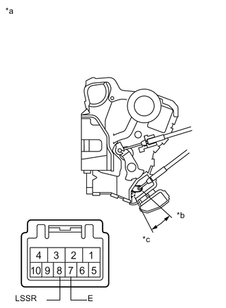
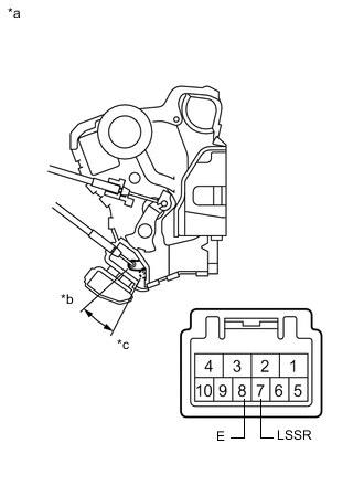
Text in Illustration *a Component without harness connected
(Front Door Lock Assembly LH)
*b Unlock *c Lock Check the operation of the door unlock detection switch.
-
Measure the resistance according to the value(s) in the table below.
Standard Resistance Tester Connection Condition Specified Condition 7 (E) - 8 (LSSR) Locked 10 kΩ or higher 7 (E) - 8 (LSSR) Unlocked Below 1 Ω If the result is not as specified, replace the front door lock assembly LH.
-
-
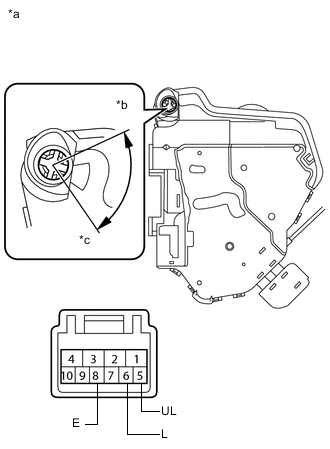
Text in Illustration *a Component without harness connected
(Front Door Lock Assembly LH)
*b Unlock *c Lock Check the operation of the door key lock and unlock switch. (for LHD)
-
Measure the resistance according to the value(s) in the table below.
Standard Resistance Tester Connection Condition Specified Condition 9 (L) - 7 (E) Turned to lock Below 1 Ω 9 (L) - 7 (E) Not turned 10 kΩ or higher 10 (UL) - 7 (E) Turned to unlock Below 1 Ω 10 (UL) - 7 (E) Not turned 10 kΩ or higher If the result is not as specified, replace the front door lock assembly LH.
-
-
-
INSPECT FRONT DOOR LOCK ASSEMBLY LH (w/ Double Locking System)
-
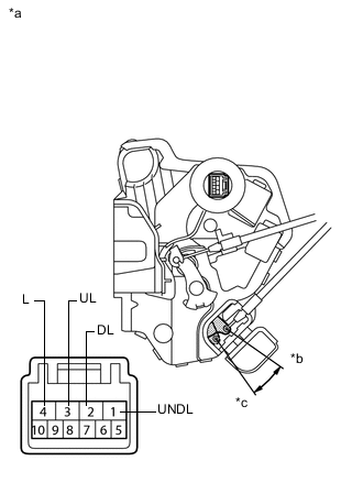
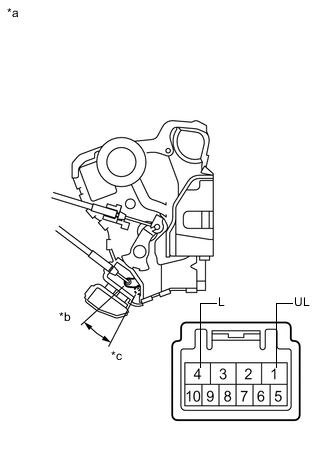
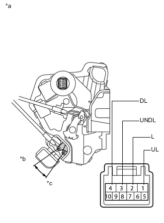
Text in Illustration *a Component without harness connected
(Front Door Lock Assembly LH)
*b Unlock *c Lock Check the operation of the door lock motor and double lock motor.
-
Apply auxiliary battery voltage and check the operation of the door lock motor and double lock motor.
OK Connection Result Auxiliary battery positive (+) → 4 (L)
Auxiliary battery negative (-) → 3 (UL)
Locks Auxiliary battery positive (+) → 3 (UL)
Auxiliary battery negative (-) → 4 (L)
Unlocks Auxiliary battery positive (+) → 2 (DL)
Auxiliary battery negative (-) → 1 (UNDL)
Sets Auxiliary battery positive (+) → 1 (UNDL)
Auxiliary battery negative (-) → 2 (DL)
Unsets Tech Tips
-
Move the door lock motor to the lock position and set the double locking system. Check that the doors cannot be unlocked by operating the control cable.
-
Move the door lock motor to the lock position and unset the double locking system. Check that the doors can be unlocked by operating the control cable.
If the result is not as specified, replace the front door lock assembly LH.
-
-
-
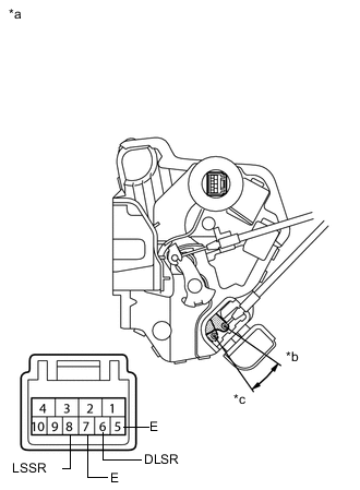
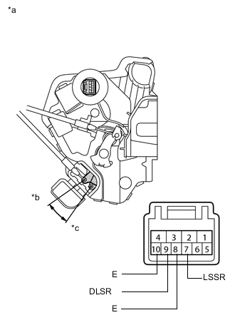
Text in Illustration *a Component without harness connected
(Front Door Lock Assembly LH)
*b Unlock *c Lock Check the operation of the door unlock detection switch and double lock position switch.
-
Measure the resistance according to the value(s) in the table below.
Standard Resistance Tester Connection Condition Specified Condition 8 (LSSR) - 7 (E) Locked 10 kΩ or higher 8 (LSSR) - 7 (E) Unlocked Below 1 Ω 6 (DLSR) - 5 (E) Unset 10 kΩ or higher 6 (DLSR) - 5 (E) Set Below 1 Ω If the result is not as specified, replace the front door lock assembly LH.
-
-
-
INSPECT FRONT DOOR LOCK ASSEMBLY RH (w/o Double Locking System)
-
Text in Illustration *a Component without harness connected
(Front Door Lock Assembly RH)
*b Unlock *c Lock Check the operation of the door lock motor.
-
Apply auxiliary battery voltage and check the operation of the door lock motor.
OK Connection Result Auxiliary battery positive (+) → Terminal 4 (L)
Auxiliary battery negative (-) → Terminal 1 (UL)
Locks Auxiliary battery positive (+) → Terminal 1 (UL)
Auxiliary battery negative (-) → Terminal 4 (L)
Unlocks If the result is not as specified, replace the front door lock assembly RH.
-
-
Text in Illustration *a Component without harness connected
(Front Door Lock Assembly RH)
*b Unlock *c Lock Check the operation of the door unlock detection switch.
-
Measure the resistance according to the value(s) in the table below.
Standard Resistance Tester Connection Condition Specified Condition 7 (LSSR) - 8 (E) Locked 10 kΩ or higher 7 (LSSR) - 8 (E) Unlocked Below 1 Ω If the result is not as specified, replace the front door lock assembly RH.
-
-
Text in Illustration *a Component without harness connected
(Front Door Lock Assembly RH)
*b Unlock *c Lock Check the resistance of the door lock and unlock switch. (for RHD)
-
Measure the resistance according to the value(s) in the table below.
Standard Resistance Tester Connection Condition Specified Condition 6 (L) - 8 (E) Turned to lock Below 1 Ω Not turned 10 kΩ or higher 5 (UL) - 8 (E) Turned to unlock Below 1 Ω Not turned 10 kΩ or higher If the result is not as specified, replace the front door lock assembly RH.
-
-
-
INSPECT FRONT DOOR LOCK ASSEMBLY RH (w/ Double Locking System)
-
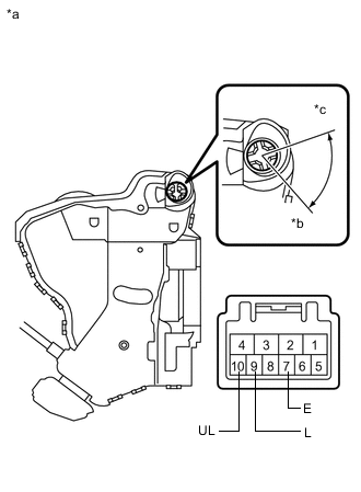
Text in Illustration *a Component without harness connected
(Front Door Lock Assembly RH)
*b Unlock *c Lock Check the operation of the door lock motor and double lock motor.
-
Apply auxiliary battery voltage and check the operation of the door lock motor and double lock motor.
OK Connection Result Auxiliary battery positive (+) → 2 (L)
Auxiliary battery negative (-) → 1 (UL)
Locks Auxiliary battery positive (+) → 1 (UL)
Auxiliary battery negative (-) → 2 (L)
Unlocks Auxiliary battery positive (+) → 4 (DL)
Auxiliary battery negative (-) → 3 (UNDL)
Sets Auxiliary battery positive (+) → 3 (UNDL)
Auxiliary battery negative (-) → 4 (DL)
Unsets Tech Tips
-
Move the door lock motor to the lock position and set the double locking system. Check that the doors cannot be unlocked by operating the control cable.
-
Move the door lock motor to the lock position and unset the double locking system. Check that the doors can be unlocked by operating the control cable.
If the result is not as specified, replace the front door lock assembly RH.
-
-
-
Text in Illustration *a Component without harness connected
(Front Door Lock Assembly RH)
*b Unlock *c Lock Check the operation of the door unlock detection switch and double lock position switch.
-
Measure the resistance according to the value(s) in the table below.
Standard Resistance Tester Connection Condition Specified Condition 7 (LSSR) - 8 (E) Locked 10 kΩ or higher 7 (LSSR) - 8 (E) Unlocked Below 1 Ω 9 (DLSR) - 10 (E) Unset 10 kΩ or higher 9 (DLSR) - 10 (E) Set Below 1 Ω If the result is not as specified, replace the front door lock assembly RH.
-
-
Text in Illustration *a Component without harness connected
(Front Door Lock Assembly RH)
*b Unlock *c Lock Check the operation of the door key lock and unlock switch. (for RHD)
-
Measure the resistance according to the value(s) in the table below.
Standard Resistance Tester Connection Condition Specified Condition 6 (L) - 8 (E) Turned to lock Below 1 Ω 6 (L) - 8 (E) Not turned 10 kΩ or higher 5 (UL) - 8 (E) Turned to unlock Below 1 Ω 5 (UL) - 8 (E) Not turned 10 kΩ or higher If the result is not as specified, replace the front door lock assembly RH.
-
-