TIRE PRESSURE WARNING SYSTEM
-
FUNCTION OF MAIN COMPONENTS
Component Function Tire Pressure Warning Valve and Transmitter
-
Detects the tire inflation pressure and temperature of the tire and transmits the measured value and ID code to the tire pressure warning ECU and receiver.
-
Transmits the acceleration rate signal from the built-in acceleration sensor to the tire pressure warning ECU and receiver to identify tire position.
Tire Pressure Warning ECU and Receiver
-
Receives the data from the tire pressure warning valve and transmitter and monitors the tire inflation pressure.
-
Outputs the respective signal to the main body ECU (multiplex network body ECU) when a drop in the tire inflation pressure, a system malfunction or the beginning of initialization is detected.
-
Using wheel speed signals from the skid control ECU and acceleration signals from the tire pressure warning valve and transmitters, the system links each tire pressure warning valve to a tire position. Then, signals are sent to the combination meter assembly to display tire pressure information on the multi-information display.
Front Tire Pressure Antenna* Receives the tire pressure warning valve and transmitter signal and transmits this data to the tire pressure warning ECU and receiver. Main Body ECU (Multiplex Network Body ECU) Receives the signal from the tire pressure warning ECU and receiver and outputs it to the combination meter assembly via CAN communication. Speed Sensor Detect the wheel speed of each of the 4 wheels and sends the 4 wheel speed signal to skid control ECU. Brake Actuator Assembly Skid Control ECU Transmits the 4 wheel speed signal to the tire pressure warning ECU and receiver. Combination Meter Assembly Transmits the vehicle speed signal to the tire pressure warning ECU and receiver. Combination Meter Assembly Tire Pressure Warning Light Warns the driver by illuminating or blinking for one minute in accordance with the signal from the tire pressure warning ECU and receiver. Multi-information Display Displays the identified tire pressure and position to inform or warn the driver. Steering Pad Switch Assembly DISP Switch Switches the information on the multi-information display to the tire pressure when pressed. *: Models with front tire pressure antenna
-
-
FUNCTION
-
Tire Inflation Pressure Display Function
-
The multi-information display shows the following to inform or warn the driver of the tire pressure:
Condition Multi-information Display* Tire pressure is normal. 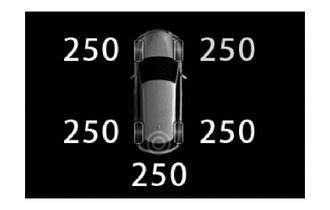
Tire pressure is below the warning threshold. 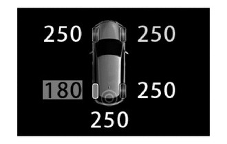
-
Tire position identification has not yet been completed.
-
There is a system malfunction.
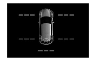
*: This illustration is an example.
-
-
Identification of the tire position is carried out when the engine switch is turned on (IG), initialization is performed, or the transmitter ID code is registered. However, under certain conditions, the tire position may not be displayed. In that case, electric wave conditions may be restored by continuously driving to enable the tire position determination.
-
Identification of the tire positions is completed by driving the vehicle at 37 km/h or more for approximately 10 to 30 minutes. After completion, the tire pressure values are updated at intervals of approximately 3 to 5 minutes. When the vehicle is stationary, the air pressure values are updated approximately once every 1.5 minutes.
-
-
Warning Function
-
When any of the following conditions are met, the tire pressure warning system illuminates the tire pressure warning light to warn the driver.
Warning Condition (Models Compliant with FMVSS138 Legal Regulations)
-
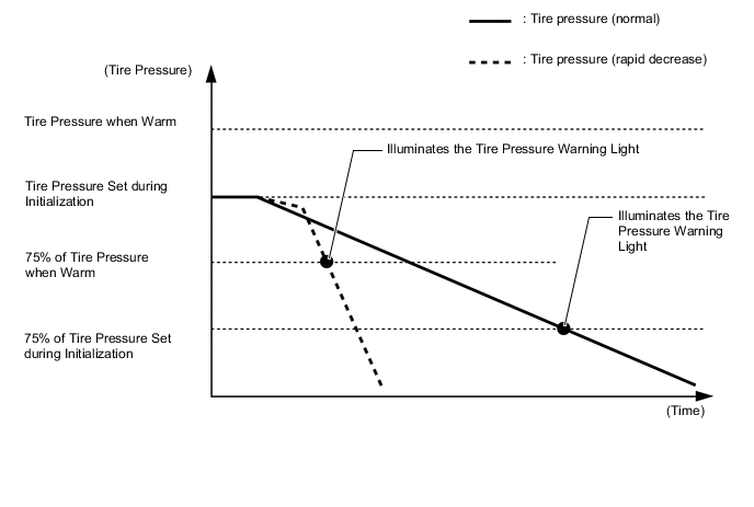
When the tire pressure decreases to approximately 75% or less of the default tire pressure set during system initialization.
Tech Tips
The warning pressure (pressure at which the tire pressure warning light illuminates) is not set to a tire pressure that is approximately 75% or less of the specified tire pressure.
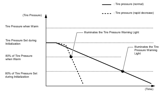
Warning Condition (Models Compliant with ECE-R64 Legal Regulations)
-
When the tire pressure decreases to approximately 80% or less of the default tire pressure set during system initialization.
-
When the tire pressure decreases rapidly (approximately 20 kPa or more over a period of several minutes) and drops below approximately 80% or less of the tire pressure when warm.
Tech Tips
When driving for a certain period of time after the system has been initialized, the system corrects the tire pressure set during initialization according to the vehicle driving conditions and sets the tire pressure when warm.
-
-
The tire pressure warning system has 2 warning methods which are used depending on the condition detected.
-
The table below shows the warning methods for the tire pressure warning light in the combination meter assembly and the multi-information display.
Detection Condition Tire Pressure Warning Light Multi-information Display*1 The tire pressure warning system has detected that the tire pressure has become lower than the warning threshold. Illuminates*2 The tire pressure warning system has detected a malfunction in the system. Stays on after blinking for 1 minute*3 *1: This illustration is an example.
*2: If the tire pressure warning light illuminates, adjust the tire pressure.
*3: If the tire pressure warning light stays on after blinking for 1 minute, the system is malfunctioning and must be repaired in order to turn off the light. For details, refer to the Repair Manual.
-
-
Initial Check Function
-
After the engine switch is tuned on (IG), the tire pressure warning ECU and receiver illuminates the tire pressure warning light for 3 seconds to check the warning light circuit.
-
-
Initialization Function
-
The warning threshold is calculated from the tire inflation pressure valve at the time of initialization and memorized in the tire pressure warning ECU and receiver. Therefore, the tire pressure warning ECU and receiver should be initialized after:
-
The recommended tire inflation pressure changes due to changes in vehicle weight, speed conditions or tire size.
-
Tire pressure warning ECU and receiver or the tire pressure warning valve and transmitter are replaced.
-
The tires are rotated on a vehicle with different recommended tire inflation pressures for the front and rear tires.
-
The tire pressure is adjusted.
-
-
After the initialization operation has completed, the tire pressure warning ECU and receiver receives an initialization signal and the tire pressure warning light illuminates slowly 3 times.
-
Before performing initialization, adjust the tire inflation pressure to the recommended pressure when the tires are cold. For details, refer to the Repair Manual.
-
The initialization operation is not used to cancel the warning. The initialization operation is used to turn off the tire pressure warning light.
-
-
-
DIAGNOSIS
-
To inform the driver when the tire pressure warning ECU and receiver detects a malfunction in the system, the tire pressure warning ECU and receiver will blink the tire pressure warning light for 1 minute, after which the light will stay on. It will also store the Diagnostic Trouble Codes (DTCs) in memory.
-
5-digit DTCs can be read by connecting the Global TechStream (GTS) to the DLC3. For details, refer to the Repair Manual.
-