METER / GAUGE SYSTEM TERMINALS OF ECU
-
COMBINATION METER SUB-ASSEMBLY
-
Measure the voltage and resistance according to the value(s) in the table below.
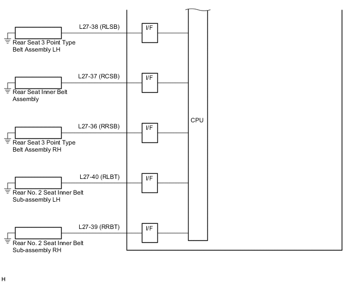
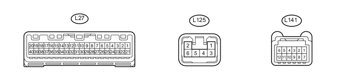
Terminal No. (Symbol) Wiring Color Terminal Description Condition Specified Condition L27-1 (B) - Body ground L - Body ground Auxiliary battery Power switch off 11 to 14 V L27-2 (IG+) - Body ground BR - Body ground Power switch signal Power switch off Below 1 V Power switch on (IG) 11 to 14 V L27-4 (HAZ) - Body ground Y - Body ground Hazard switch (Hazard warning signal switch assembly) Power switch on (IG), hazard warning lights off 11 to 14 V Power switch on (IG), hazard warning lights on Below 1 V L27-5 (LP) - Body ground B - Body ground Security warning signal Security warning off 11 to 14 V Security warning blinking Below 1 V ←→ 11 to 14 V L27-6 (EFI) - Body ground LG - Body ground MIL (Check engine warning light) signal Power switch on (IG), MIL off (Check engine warning light) 11 to 14 V Power switch on (IG), MIL on (Check engine warning light) Below 1 V L27-7 (S) - Body ground V - Body ground Oil pressure signal Power switch on (IG), oil pressure warning light off 11 to 14 V Power switch on (IG), oil pressure warning light on Below 1 V L27-8 (TWS3) - L27-9 (E2) B - GR Engine coolant temperature sensor signal Power switch on (IG), water temperature warning light off 4.9 to 5.1 V Power switch on (IG), water temperature warning light on Below 1 V L27-9 (E2) - Body ground GR - Body ground Ground Always Below 1 Ω L27-10 (STRG) - Body ground
*1
B - Body ground Touch tracer display (Steering pad switch assembly) Always Pulse generation L27-11 (ES) - Body ground BR - Body ground Ground Always Below 1 Ω L27-12 (L) - L27-13 (ES 2) B - R Fuel signal Power switch on (IG), fuel level full Below 1 V Power switch on (IG), fuel level low 4.5 to 9 V L27-13 (ES 2) - Body ground R - Body ground Ground Always Below 1 Ω L27-15 (+S) - Body ground V - Body ground Speed signal for other system (Output) Power switch on (IG), wheel being rotated. Pulse generation
(See waveform 1)
L27-16 (SI) - Body ground BR - Body ground Speed signal for other system (Input) Power switch on (IG), wheel being rotated. Pulse generation
(See waveform 1)
L27-17 (B) - Body ground P - Body ground RH turn indicator light signal Power switch on (IG), RH turn signal indicator light off Below 1 V Power switch on (IG), RH turn signal indicator light blinking Below 1 V ←→ 11 to 14 V L27-18 (B) - Body ground R - Body ground LH turn indicator light signal Power switch on (IG), LH turn signal indicator light off Below 1 V Power switch on (IG), LH turn signal indicator light blinking Below 1 V ←→ 11 to 14 V L27-19 (CANH) - Body ground SB - Body ground CAN communication line - - L27-20 (CANL) - Body ground G - Body ground CAN communication line - - L27-21 (HOUR) - Body ground B - Body ground Hour adjust switch (Hazard warning signal switch assembly) signal Power switch on (IG), hour adjust switch not pressed 11 to 14 V Power switch on (IG), hour adjust switch pressed Below 1 V L27-22 (MIN) - Body ground P - Body ground Minute adjust switch (Hazard warning signal switch assembly) signal Power switch on (IG), minute adjust switch not pressed 11 to 14 V Power switch on (IG), minute adjust switch pressed Below 1 V L27-23 (RST) - Body ground R - Body ground Second adjust switch (Hazard warning signal switch assembly) signal Power switch on (IG), second adjust switch not pressed 11 to 14 V Power switch on (IG), second adjust switch pressed Below 1 V L27-24 (ODO) - Body ground
*2
GR - Body ground ODO switch (Steering pad switch assembly) signal Power switch on (IG), ODO switch not pressed 11 to 14 V Power switch on (IG), ODO switch pressed Below 1 V L27-25 (MSSL) - Body ground
*2
W - Body ground DISP switch (Steering pad switch assembly) signal Power switch on (IG), DISP switch not pressed 11 to 14 V Power switch on (IG), DISP switch pressed Below 1 V L27-26 (TC O) - Body ground SB - Body ground Rheostat switch / pattern select switch (Hazard warning signal switch assembly) signal Power switch on (IG), rheostat switch / pattern select switch not pressed 11 to 14 V Power switch on (IG), rheostat switch / pattern select switch pressed Below 1 V L27-27 (LVWG) - Body ground L - Body ground Headlight leveling signal Power switch on (IG), leveling indicator light off 11 to 14 V Power switch on (IG), leveling indicator light on Below 1 V L27-29 (SW) - Body ground P*3 - Body ground
R*4 - Body ground
Front passenger side seat belt buckle switch signal Power switch on (IG), front passenger seat occupied, front passenger side seat belt unfastened Below 1 V Power switch on (IG), front passenger seat occupied, front passenger side seat belt fastened 11 to 14 V L27-36 (RRSB) - Body ground R - Body ground Rear seat 3 point type belt assembly RH signal Power switch on (IG), rear seat 3 point type belt assembly RH unfastened Below 1 V Power switch on (IG), rear seat 3 point type belt assembly RH fastened 11 to 14 V L27-37 (RCSB) - Body ground L - Body ground Rear seat inner belt assembly signal Power switch on (IG), rear seat inner belt assembly unfastened Below 1 V Power switch on (IG), rear seat inner belt assembly fastened 11 to 14 V L27-38 (RLSB) - Body ground Y - Body ground Rear seat 3 point type belt assembly LH signal Power switch on (IG), rear seat 3 point type belt assembly LH unfastened Below 1 V Power switch on (IG), rear seat 3 point type belt assembly LH fastened 11 to 14 V L27-39 (RRBT) - Body ground B - Body ground Rear No. 2 seat inner belt sub-assembly RH signal Power switch on (IG), rear No. 2 seat inner belt sub-assembly RH unfastened Below 1 V Power switch on (IG), rear No. 2 seat inner belt sub-assembly RH fastened 11 to 14 V L27-40 (RLBT) - Body ground W - Body ground Rear No. 2 seat inner belt sub-assembly LH signal Power switch on (IG), rear No. 2 seat inner belt sub-assembly LH unfastened Below 1 V Power switch on (IG), rear No. 2 seat inner belt sub-assembly LH fastened 11 to 14 V L125-2 (B) - Body ground SB - Body ground Auxiliary battery Power switch off 11 to 14 V L125-3 (LL) - Body ground Y - Body ground LH turn indicator light signal Power switch on (IG), LH turn indicator light off 11 to 14 V Power switch on (IG), LH turn indicator light blinking Below 1 V ←→ 11 to 14 V L125-5 (LR) - Body ground SB - Body ground RH turn indicator light signal Power switch on (IG), RH turn indicator light off 11 to 14 V Power switch on (IG), RH turn indicator light blinking Below 1 V ←→ 11 to 14 V L141-1 (12V) - Body ground
*1
B - Body ground Power switch signal Power switch off Below 1 V Power switch on (IG) 11 to 14 V L141-7 (TX+) - Body ground
*1
P - Body ground AVC-LAN communication signal Power switch on (IG) Pulse generation L141-8 (TX-) - Body ground
*1
R - Body ground AVC-LAN communication signal Power switch on (IG) Pulse generation L141-9 (SIH) - Body ground
*1
L - Body ground AVC-LAN communication signal Power switch on (IG) Pulse generation L141-10 (SIL) - Body ground
*1
BE - Body ground AVC-LAN communication signal Power switch on (IG) Pulse generation L141-12 (GND) - Body ground
*1
G - Body ground Ground Always Below 1 Ω
-
*1: w/ Headup Display
-
*2: w/o Headup Display
-
*3: for LHD
-
*4: for RHD
If the result is not as specified, the combination meter sub-assembly may have a malfunction.
-
-
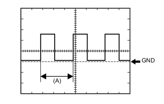
Waveform 1 (Reference):
Item Condition Tool setting 5 V/DIV., 20 ms./DIV. Vehicle condition Wheel being rotated Tech Tips
When the system is functioning normally, one wheel revolution generates 4 pulses. As the vehicle speed increases, the width indicated by (A) in the illustration narrows.
-
-
HEADUP DISPLAY (COMBINATION METER MIRROR ECU) (w/ Headup Display)
-
Measure the voltage and resistance according to the value(s) in the table below.

Terminal No. (Symbol) Wiring Color Terminal Description Condition Specified Condition L149-1 (12V) - Body ground B - Body ground Power switch signal Power switch off Below 1 V Power switch on (IG) 10 to 16 V L149-3 (SIH) - Body ground P - Body ground AVC-LAN communication signal Power switch on (IG) Pulse generation L149-4 (SIL) - Body ground R - Body ground AVC-LAN communication signal Power switch on (IG) Pulse generation L149-5 (TX+) - Body ground L - Body ground AVC-LAN communication signal Power switch on (IG) Pulse generation L149-6 (TX-) - Body ground BE - Body ground AVC-LAN communication signal Power switch on (IG) Pulse generation L149-8 (GND) - Body ground G - Body ground Ground Always Below 1 Ω L149-13 (HUDI) - Body ground L - Body ground Headup display switch assembly signal (Headup display main switch indicator light) Power switch on (IG), headup display main switch indicator light comes on 6.2 to 10.6 V Power switch on (IG), headup display main switch indicator light goes off Below 1 V L149-14 (HUDU) - Body ground B - Body ground Headup display switch assembly signal (Headup display tilt down switch, Headup display SET switch) Power switch on (IG), headup display tilt up or down switch not pressed 4.5 to 5.5 V Power switch on (IG), headup display tilt up switch pressed 2.2 to 2.8 V Power switch on (IG), headup display tilt down switch pressed 1.2 to 1.6 V Power switch on (IG), headup display SET switch not pressed 4.5 to 5.5 V Power switch on (IG), headup display SET switch pressed 3.0 to 3.8 V L149-15 (HUDO) - Body ground G - Body ground Headup display switch assembly signal (Headup display rheostat switch, Headup dispaly main switch) Power switch on (IG), headup display rheostat up or down switch not pressed 4.5 to 5.5 V Power switch on (IG), headup display rheostat up switch pressed 2.2 to 2.8 V Power switch on (IG), headup display rheostat down switch pressed 1.2 to 1.6 V Power switch on (IG), headup display main switch not pressed 4.5 to 5.5 V Power switch on (IG), headup display main switch pressed Below 1 V L149-16 (E) - Body ground BE - Body ground Ground Always Below 1 Ω
-
-
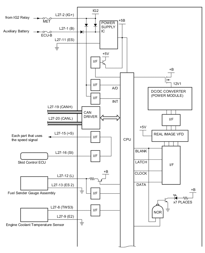
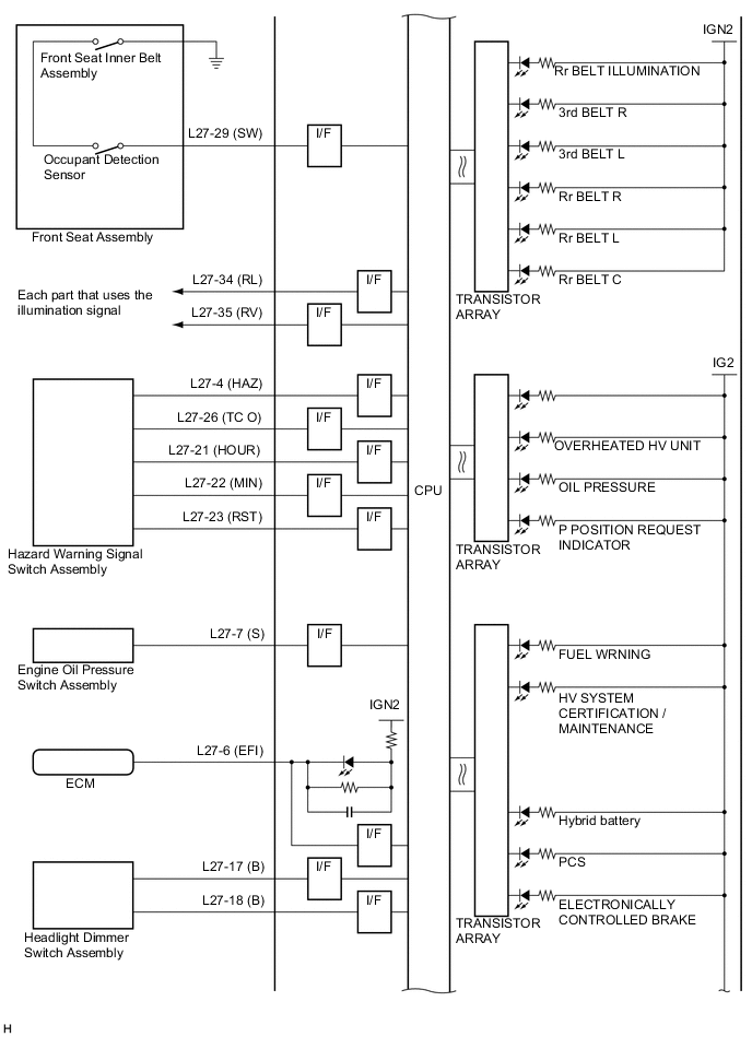
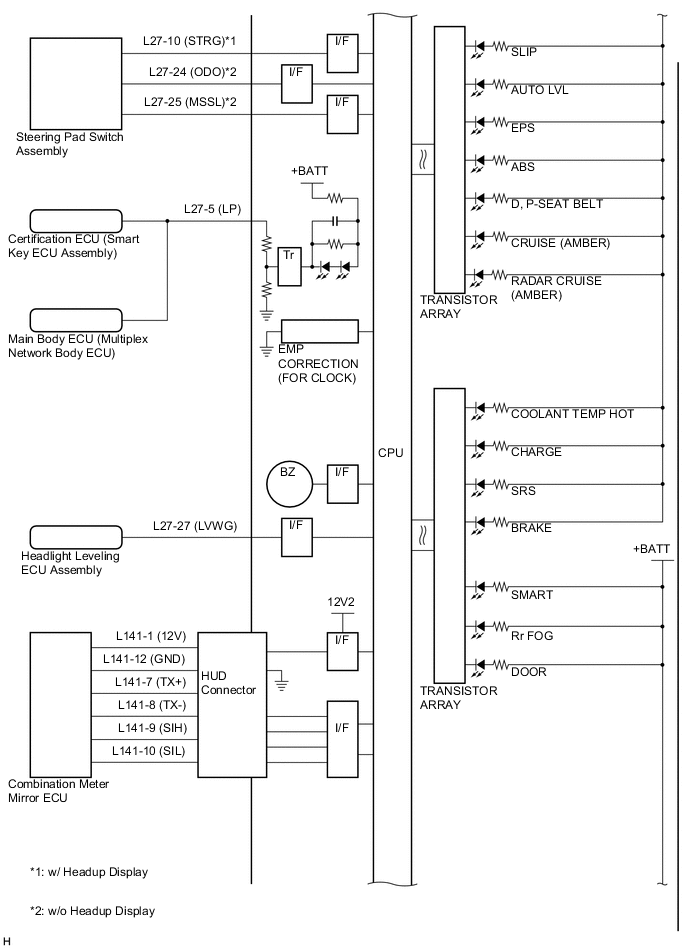
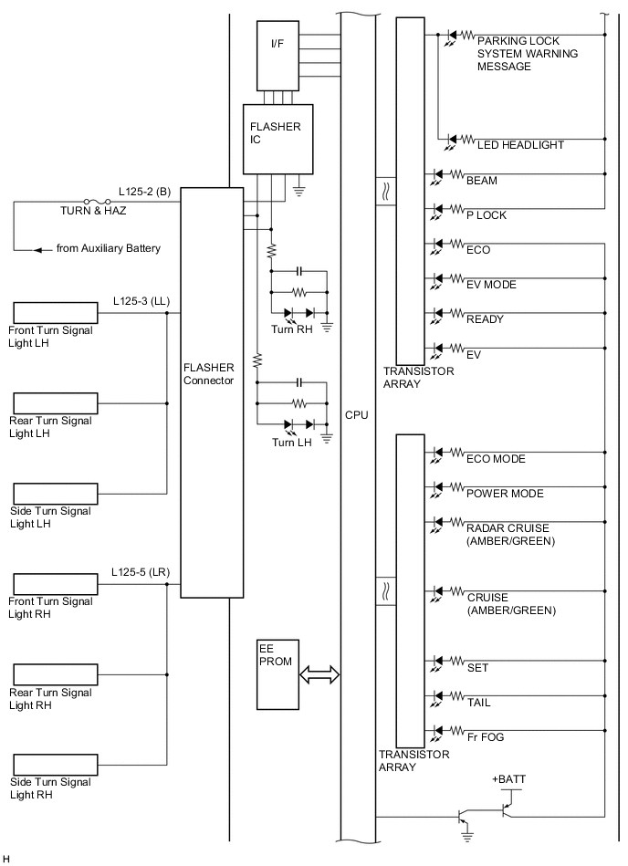
COMBINATION METER SUB-ASSEMBLY INNER CIRCUIT