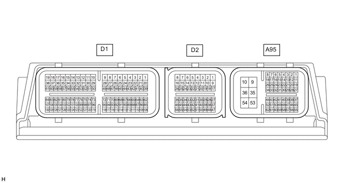
ENTRY AND START SYSTEM(for Start Function) TERMINALS OF ECU
-
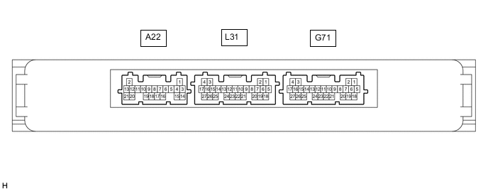
CHECK CERTIFICATION ECU (SMART KEY ECU ASSEMBLY)
-
Disconnect the G71, L31 and A22 certification ECU (smart key ECU assembly) connectors.
-
Measure the voltage and resistance according to the value(s) in the table below.
Tech Tips
Measure the values on the wire harness side with the connector disconnected.
Tester Connection Wiring Color Input/Output Terminal Description Condition Specified Condition Related Data List Item A22-16 (NE) - Body ground W - Body ground Input Engine speed signal Always 10 kΩ or higher Power Source Control
-
Engine Condition
L31-25 (STP1) - Body ground R - Body ground Input Stop light switch signal Brake pedal depressed → Brake pedal released 9 V or higher → 1 V or less Power Source Control
-
Stop Light Switch1
G71-4 (+B) - G71-18 (E) W - W-B Input Power source Always 11 to 14 V - G71-15 (CUTB) - Body ground P - Body ground Input Dark current cut pin* Always 11 to 14 V - G71-18 (E) - Body ground W-B - Body ground - Ground Always Below 1 Ω - G71-21 (SSW2) - Body ground G - Body ground Input SSW2 contact signal
Tech Tips
Backup for SSW1. Behaves the same way as SSW1.
Engine switch pushed → Engine switch not pushed Below 15 Ω → 10 kΩ or higher Power Source Control
-
Start Switch2
G71-23 (SSW1) - Body ground V - Body ground Input SSW1 contact signal Engine switch pushed → Engine switch not pushed Below 15 Ω → 10 kΩ or higher Power Source Control
-
Start Switch1
G71-19 (SPD) - Body ground SB - Body ground Input Vehicle speed signal Always 30 kΩ or higher Power Source Control
-
Vehicle Speed Signal
-
*: In order to prevent the vehicle battery from being depleted when the vehicle is shipped long distances, a fuse that cuts unnecessary electrical load while the vehicle is being shipped is installed in the circuit. If the fuse is removed, the circuit becomes open. If the fuse that is between the vehicle battery and terminal CUTB is removed and the circuit is open, the certification ECU (smart key ECU assembly) changes to a certain control mode (example: the transmission of radio waves every 0.25 seconds, which form the detection area, stops).
-
-
Reconnect the G71, L31 and A22 certification ECU (smart key ECU assembly) connectors.
-
Measure the voltage and resistance and check for pulses according to the value(s) in the table below.
Tester Connection Wiring Color Input/Output Terminal Description Condition Specified Condition Related Data List Item A22-20 (STA) - G71-18 (E) R - W-B Input When starting the engine, this monitors the voltage sent from terminal STAR to the starter relay to judge whether the engine is "being started". Engine switch pressed and held with brake pedal depressed (starter on) → Approximately 1 second after engine switch released (starter off) 6 V or higher*2 → 1.0 V or less - A22-9 (STAR) - G71-18 (E) GR - W-B Input / Output Outputs voltage to the starter relay
-
Outputs voltage (12 V) to the starter relay when starting the engine. (Max. 30 seconds. Turns off when an engine speed of 1000 rpm.)
Tech Tips
When Hi is selected, a start request signal (STAR) will not be output even though a start request signal (STSW) is input.
Engine switch pressed and held with brake pedal depressed (starter on) → Approximately 1 second after engine switch released (starter off) 6 V or higher*2 → 1.0 V or less - A22-16 (NE) - G71-18 (E) W - W-B Input Engine speed signal Idling (engine warmed up) Pulse generation
(See waveform 8)
Power Source Control
-
Engine Condition
L31-25 (STP1) - G71-18 (E) R - W-B Input Stop light switch signal Brake pedal released → Brake pedal depressed 1 V or less → 9 V or higher Power Source Control
-
Stop Light Switch1
G71-14 (SLP) - G71-18 (E) R - W-B Input Steering lock position signal Steering locked → Steering unlocked 11 to 14 V → 1.5 V or less Power Source Control
-
Steering Unlock Switch
G71-25 (SLR+) - G71-18 (E) G - W-B Output Steering lock motor operation command signal
(Steering lock motor operation permission signal sent from the certification ECU (smart key ECU assembly))
When a door is opened, the steering lock motor will be operated if all of the following conditions are met:
-
The steering is unlocked.
-
The engine switch is off.
-
The shift state park (P).
Pulse generation
(See waveform 1)
- G71-13 (LIN) - G71-18 (E) G - W-B Input/Output LIN communication line Engine switch on (IG) Pulse generation Entry&Start
-
Steering Lock Start Cond
G71-22 (P) - G71-18 (E) LG - W-B Input P position signal Procedure:
-
Engine switch on (IG)
-
Shift state park (P)
Pulse generation
(See waveform 7)
Power Source Control
-
Shift P Signal
G71-21 (SSW2) - G71-18 (E) G - W-B Input SSW2 contact signal
Tech Tips
Backup for SSW1. Behaves the same way as SSW1.
Engine switch not pushed → Engine switch pushed 9 V or higher → 1 V or less Power Source Control
-
Start Switch2
G71-23 (SSW1) - G71-18 (E) V - W-B Input SSW1 contact signal Engine switch not pushed → Engine switch pushed 9 V or higher → 1 V or less Power Source Control
-
Start Switch1
G71-16 (ACCD) - G71-18 (E) SB- W-B Output ACC signal Engine switch off → Engine switch on (ACC) 1 V or less → 8.5 V or higher Power Source Control
-
ACC Relay Monitor
G71-17 (IG1D) - G71-18 (E) B - W-B Output IG1 signal Engine switch on (ACC) → Engine switch on (IG) 1 V or less → 9 V or higher Power Source Control
-
IG Relay Monitor (Outside)
G71-19 (SPD) - G71-18 (E) SB - W-B Input Vehicle speed signal Vehicle being driven at approximately 5 km/h (3 mph) Pulse generation
(See waveform 2)
Power Source Control
-
Vehicle Speed Signal
G71-8 (CLG5) - G71-18 (E) GR - W-B Output Output to No. 1 indoor electrical key antenna assembly (front floor) Procedure:
-
Engine switch off
-
Electrical key transmitter sub-assembly not inside vehicle
-
Within 30 seconds of closing any door
Pulse generation
(See waveform 3)
- G71-9 (CG5B) - G71-18 (E) B - W-B Output Output to No. 1 indoor electrical key antenna assembly (front floor) (terminal on opposite side of component from CLG5 output terminal) Procedure:
-
Engine switch off
-
Electrical key transmitter sub-assembly not inside vehicle
-
Within 30 seconds of closing any door
Pulse generation
(See waveform 3)
- L31-5 (CLG6) - G71-18 (E) W - W-B Output Output to No. 1 indoor electrical key antenna assembly (rear floor) Procedure:
-
Engine switch off
-
Electrical key transmitter sub-assembly not inside vehicle
-
Within 30 seconds of closing any door
Pulse generation
(See waveform 3)
- L31-6 (CG6B) - G71-18 (E) L - W-B Output Output to No. 1 indoor electrical key antenna assembly (rear floor) (terminal on opposite side of component from CLG6 output terminal) Procedure:
-
Engine switch off
-
Electrical key transmitter sub-assembly not inside vehicle
-
Within 30 seconds of closing any door
Pulse generation
(See waveform 3)
- G71-5 (TXCT) - G71-11 (AGND) LG - L Output Signal output to transponder key amplifier Engine switch off, brake pedal not depressed, 30 seconds or more elapsed after driver door opened and then closed Below 1 V Entry&Start
-
BCC Malfunction
-
Abnormal Status
-
Different Encrypt Code
-
Different Serial Number
-
Frame Error
-
Response
G71-6 (CODE) - G71-11 (AGND) Y - L Input Signal input from transponder key amplifier Engine switch off, brake pedal not depressed, 30 seconds or more elapsed after driver door opened and then closed Below 1 V G71-7 (VC5) - G71-11 (AGND) L - L Output Transponder key amplifier power supply Engine switch off, brake pedal not depressed, 30 seconds or more elapsed after driver door opened and then closed Below 1 V G71-11 (AGND) - Body ground L - Body ground - Transponder key amplifier ground Always Below 1 Ω G71-5 (TXCT) - G71-11 (AGND) LG - L Output Signal output to transponder key amplifier
(Code sent from certification ECU (smart key ECU assembly) to transponder key amplifier built into engine switch, and then transmitted by transponder key amplifier antenna as radio waves)
Engine switch off, key not in cabin, within 30 seconds after engine switch pressed Pulse generation
(See waveform 4)
Entry&Start
-
BCC Malfunction
-
Abnormal Status
-
Different Encrypt Code
-
Different Serial Number
-
Frame Error
-
Response
Tech Tips
If immobiliser key code verification communication is not performed correctly, the malfunction may be indicated by one or more of the Data List items listed above
G71-6 (CODE) - G71-11 (AGND) Y - L Input Signal input from transponder key amplifier
(Radio waves from transponder key amplifier built into engine switch used to detect key information. Key information then sent to certification ECU (smart key ECU assembly))
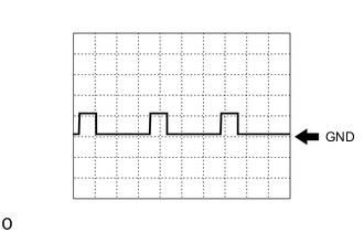
Engine switch off, engine switch pressed with key held near engine switch*1 Pulse generation
(See waveform 5)
G71-7 (VC5) - G71-11 (AGND) L - L Output Transponder key amplifier power supply
(Power supplied from certification ECU (smart key ECU assembly) when transponder key amplifier built into engine switch activated)
Engine switch off, key not in cabin, within 30 seconds after engine switch pressed Pulse generation
(See waveform 6)
G71-20 (IND) - G71-18 (E) P - W-B Output Security indicator output Engine switch off → on (IG) Pulse generation → Below 2 V - Tech Tips
-
The waveform of the steering lock actuator motor stopped can be checked without performing any particular operation.
-
The waveform of the steering lock actuator motor operating can be checked if either of the following operations is performed:
-
To unlock the steering, bring the electrical key transmitter sub-assembly into the cabin and turn the engine switch on (ACC) or on (IG).
-
To lock the steering, open a door with the engine switch off and the shift state park (P).
-
*1: Remove the transmitter battery before performing this inspection.
-
*2: While the engine is cranking, the battery voltage may drop to approximately 6 V.
-
-
Using an oscilloscope, check the waveform of the ECU.
Note
The oscilloscope waveform shown in the illustration is an example for reference only. Noise, chattering, etc. are not shown.
-
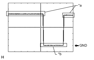
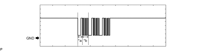
*a Steering lock motor not operating *b Steering lock motor operating Waveform 1
Item Content Tester Connection G71-25 (SLR+) - G71-18(E) Tool Setting 2 V/DIV., 200 ms./DIV. Condition When a door is opened, the steering lock motor will be operated if all of the following conditions are met:
-
The steering is unlocked.
-
The engine switch is off.
-
The shift state park (P).
-
-
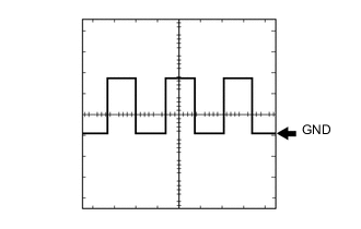
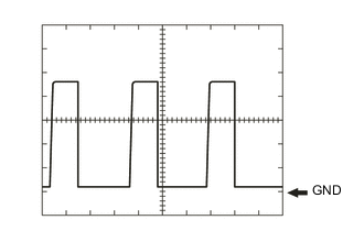
Waveform 2
Item Content Tester Connection G71-19 (SPD) - G71-18(E) Tool Setting 5 V/DIV., 20 ms./DIV. Condition Vehicle being driven at approximately 5 km/h (3 mph) Tech Tips
The wavelength becomes shorter as the vehicle speed increases.
-
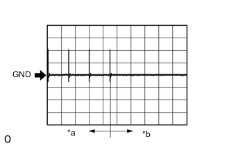
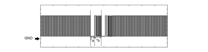
*a For 30 seconds after any door closed *b After 30 seconds or more have elapsed since any door closed Waveform 3
Item Content Tester Connection G71-8 (CLG5) - G71-18 (E)
G71-9 (CG5B) - G71-18 (E)
L31-5 (CLG6) - G71-18 (E)
L31-6 (CG6B) - G71-18 (E)
Tool Setting 2 V/DIV., 500 ms./DIV. Condition Procedure:
-
Engine switch off
-
Electrical key transmitter sub-assembly not inside vehicle
-
Within 30 seconds of closing any door
-
-

Waveform 4
Item Content Tester Connection G71-5 (TXCT) - G71-11 (AGND) Tool Setting 2 V/DIV., 20 ms./DIV. Condition Engine switch off, key not in cabin, within 30 seconds after engine switch pressed -
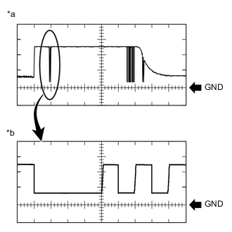
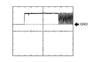
*a Waveform *b Waveform (detail) Waveform 5
Item Content Tester Connection G71-6 (CODE) - G71-11 (AGND) Tool Setting
-
Waveform:
2 V/DIV., 20 ms./DIV.
-
Waveform (detail):
2 V/DIV., 100 μs./DIV.
Condition Engine switch off, engine switch pressed with key held near engine switch* Tech Tips
*: Remove the transmitter battery before performing this inspection.
-
-

Waveform 6
Item Content Tester Connection G71-7 (VC5) - G71-11 (AGND) Tool Setting 2 V/DIV., 200 ms./DIV. Condition Engine switch off, key not in cabin, within 30 seconds after engine switch pressed -
Waveform 7
Item Content Tester Connection G71-22 (P) - G71-18 (E) Tool Setting 10 V/DIV., 10 ms./DIV. Condition Procedure:
-
Engine switch on (IG)
-
Shift state park (P)
Tech Tips
The waveform will vary depending on the shift state.
-
-
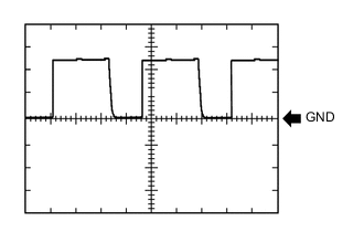
Waveform 8
Item Content Tester Connection A22-16 (NE) - G71-18 (E) Tool Setting 2 V/DIV., 2 ms./DIV. Condition Idling (engine warmed up) Tech Tips
The wavelength becomes shorter as the engine speed increases.
-
-
-
CHECK STEERING LOCK ECU (STEERING LOCK ACTUATOR OR UPPER BRACKET ASSEMBLY)

-
Disconnect the G22 steering lock ECU (steering lock actuator or upper bracket assembly) connector.
-
Measure the voltage and resistance according to the value(s) in the table below.
Tech Tips
Measure the values on the wire harness side with the connector disconnected.
Tester Connection Wiring Color Input/Output Terminal Description Condition Specified Condition Related Data List Item G22-1 (GND) - Body ground W-B - Body ground - Ground Always Below 1 Ω - G22-6 (IG2) - G22-1 (GND) R - W-B Input Power source mode signal Engine switch off → Engine switch on (IG) Below 1 V → 11 to 14 V - G22-7 (B) - Body ground B - Body ground Input Power source Always 11 to 14 V - -
Reconnect the G22 steering lock ECU (steering lock actuator or upper bracket assembly) connector.
-
Measure the voltage and puless according to the value(s) in the table below.
Tester Connection Wiring Color Input/Output Terminal Description Condition Specified Condition Related Data List Item G22-4 (SLP1) - G22-1 (GND) W - W-B Output Steering lock bar position signal (output signal from steering unlock sensor) Steering locked → unlocked 11 to 14 V → Below 1.5 V Entry&Start
-
Sensor Value
G22-5 (LIN) - G22-1 (GND) V - W-B Input/Output LIN communication line Engine switch on (IG) Pulse generation Entry&Start
-
Steering Lock Start Cond
-
-
Check for pulses according to the value(s) in the table below.
Tester Connection Wiring Color Wiring Color Terminal Description Condition Specified Condition Related Data List Item G22-3 (IGE) - G22-1 (GND) G - W-B Input Steering lock motor activation command signal Any door opened when conditions below met, and then steering lock motor activated:
-
Shift state park (P)
-
Steering lock unlocked in advance by carrying key and turning engine switch on (IG)
-
After above conditions met, engine switch turned off
Pulse generation
(see waveform 1)
Entry&Start
-
Power Supply Short
-
Unlock Request Receive
-
Lock Request Receive
Tech Tips
-
When taking measurements when the lock motor is stopped, it is not necessary to perform any operations.
-
In order to take measurements when the lock motor is operating, perform either of the following operations:
-
To unlock the steering, carry the key and turn the engine switch on (ACC) or on (IG).
-
To lock the steering, turn the engine switch off with the shift state park (P), and then open a door.
-
-
Using an oscilloscope, check the waveform of the ECU.
Note
The oscilloscope waveform shown in the illustration is an example for reference only. Noise, chattering, etc. are not shown.
-
*a Steering Lock Motor not Operating *b Steering Lock Motor Operating Waveform 1
Item Content Tester Connection G22-3 (IGE) - G22-1 (GND) Tool Setting 2 V/DIV., 200 ms./DIV. Condition Any door opened when conditions below met, and then steering lock motor activated:
-
Shift state park (P)
-
Steering lock unlocked in advance by carrying key and turning engine switch on (IG)
-
After above conditions met, engine switch turned off
-
-
-
-
CHECK ID CODE BOX (IMMOBILISER CODE ECU)

-
Disconnect the G58 ID code box (immobiliser code ECU) connector.
-
Measure the voltage and resistance according to the value(s) in the table below.
Tech Tips
Measure the values on the wire harness side with the connector disconnected.
Tester Connection Wiring Color Input/Output Terminal Description Condition Specified Condition Related Data List Item G58-1 (+B) - Body ground LA-GR - Body ground Input Power source Always 11 to 14 V - G58-5 (GND) - Body ground LA - Body ground - Ground Always Below 1 Ω -
Reconnect the G58 ID code box (immobiliser code ECU) connector.
-
Measure the voltage and check for pulses according to the value(s) in the table below.
Tester Connection Wiring Color Input/Output Terminal Description Condition Specified Condition Related Data List Item G58-3 (EFII) - G58-5 (GND) V - LA Input EFI communication input
(Signal input from ECM to ID code box (immobiliser code ECU))
Engine switch off 11 to 14 V Entry&Start
-
EFI Code Receive
-
Engine Start Request
G58-3 (EFII) - G58-5 (GND) V - LA Input EFI communication input
(Signal input from ECM to ID code box (immobiliser code ECU))
Within 3 seconds of engine start or within 3 seconds of engine switch turned on (IG) after cable disconnected and reconnected to battery Pulse generation
(See waveform 1)
G58-4 (EFIO) - G58-5 (GND) LG - LA Output EFI communication output
(Signal output from ID code box (immobiliser code ECU) to ECM)
Engine switch off Below 1 V G58-4 (EFIO) - G58-5 (GND) LG - LA Output EFI communication output
(Signal output from ID code box (immobiliser code ECU) to ECM)
Within 3 seconds of engine start or within 3 seconds of engine switch turned on (IG) after cable disconnected and reconnected to battery Pulse generation
(See waveform 2)
G58-2 (LIN1) - G58-5 (GND) L - LA Input/Output LIN communication line Engine switch on (IG) Pulse generation Entry&Start
-
Steering Lock Start Cond
-
-
Using an oscilloscope, check the waveform of the ECU.
Note
The waveform shown in the illustration is an example for reference only. Noise, chattering, etc. are not shown.
-
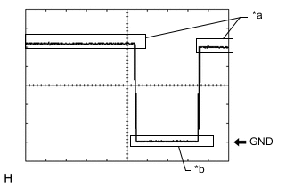
Waveform 1
*a Approximately 160 ms *b Approximately 270 ms Item Content Tester Connection G58-3 (EFII) - G58-5 (GND) Tool Setting 2 V/DIV., 500 ms./DIV. Condition Within 3 seconds of engine start or within 3 seconds of engine switch turned on (IG) after cable disconnected and reconnected to battery -
Waveform 2
*a Approximately 160 ms *b Approximately 270 ms Item Content Tester Connection G58-4 (EFIO) - G58-5 (GND) Tool Setting 2 V/DIV., 500 ms./DIV. Condition Within 3 seconds of engine start or within 3 seconds of engine switch turned on (IG) after cable disconnected and reconnected to battery
-
-
-
CHECK ECM (for 8GR-FKS)

-
Measure the voltage and resistance and check for pulses according to the value(s) in the table below.
Tester Connection Wiring Color Input/Output Terminal Description Condition Specified Condition Related Data List Item A56-1 (BATT) - D65-53 (E1) B - W-B Input Power source Always 11 to 14 V - D65-53 (E1) - Body ground W-B - Body ground - Ground Always Below 1 Ω - A56-45 (IMO) - D65-53 (E1) P - W-B Output EFI communication output
(Signal output from ECM to ID code box (immobiliser code ECU))
Engine switch off 11 to 14 V Entry&Start
-
EFI Code Receive
-
Engine Start Request
A56-45 (IMO) - D65-53 (E1) P - W-B Output EFI communication output
(Signal output from ECM to ID code box (immobiliser code ECU))
Within 3 seconds of engine start or within 3 seconds of engine switch turned on (IG) after cable disconnected and reconnected to battery Pulse generation
(See waveform 1)
A56-59 (IMI) - D65-53 (E1) LG - W-B Input EFI communication input
(Signal input from ID code box (immobiliser code ECU) to ECM)
Engine switch off Below 1 V A56-59 (IMI) - D65-53 (E1) LG - W-B Input EFI communication input
(Signal input from ID code box (immobiliser code ECU) to ECM)
Within 3 seconds of engine start or within 3 seconds of engine switch turned on (IG) after cable disconnected and reconnected to battery Pulse generation
(See waveform 2)
-
-
Using an oscilloscope, check the waveform of the ECU.
Note
The waveform shown in the illustration is an example for reference only. Noise, chattering, etc. are not shown.
-
Waveform 1
*a Approximately 160 ms *b Approximately 270 ms Item Content Tester Connection A56-45 (IMO) - D65-53 (E1) Tool Setting 2 V/DIV., 500 ms./DIV. Condition Within 3 seconds of engine start or within 3 seconds of engine switch turned on (IG) after cable disconnected and reconnected to battery -
Waveform 2
*a Approximately 160 ms *b Approximately 270 ms Item Content Tester Connection A56-59 (IMI) - D65-53 (E1) Tool Setting 2 V/DIV., 500 ms./DIV. Condition Within 3 seconds of engine start or within 3 seconds of engine switch turned on (IG) after cable disconnected and reconnected to battery
-
-
-
CHECK ECM (for V35A-FTS)
-
Measure the voltage and resistance and check for pulses according to the value(s) in the table below.
Tester Connection Wiring Color Input/Output Terminal Description Condition Specified Condition Related Data List Item D2-1 (BATT) - A95-9 (E1) G - B Input Power source Always 11 to 14 V - A95-9 (E1) - Body ground B - Body ground - Ground Always Below 1 Ω - A95-37 (IMO) - A95-9 (E1) P - B Output EFI communication output
(Signal output from ECM to ID code box (immobiliser code ECU))
Engine switch off 11 to 14 V Entry&Start
-
EFI Code Receive
-
Engine Start Request
A95-37 (IMO) - A95-9 (E1) P - B Output EFI communication output
(Signal output from ECM to ID code box (immobiliser code ECU))
Within 3 seconds of engine start or within 3 seconds of engine switch turned on (IG) after cable disconnected and reconnected to battery Pulse generation
(See waveform 1)
A95-38 (IMI) - A95-9 (E1) LG - B Input EFI communication input
(Signal input from ID code box (immobiliser code ECU) to ECM)
Engine switch off Below 1 V A95-38 (IMI) - A95-9 (E1) LG - B Input EFI communication input
(Signal input from ID code box (immobiliser code ECU) to ECM)
Within 3 seconds of engine start or within 3 seconds of engine switch turned on (IG) after cable disconnected and reconnected to battery Pulse generation
(See waveform 2)
-
-
Using an oscilloscope, check the waveform of the ECU.
Note
The waveform shown in the illustration is an example for reference only. Noise, chattering, etc. are not shown.
-
Waveform 1
*a Approximately 160 ms *b Approximately 270 ms Item Content Tester Connection A95-37 (IMO) - A95-9 (E1) Tool Setting 2 V/DIV., 500 ms./DIV. Condition Within 3 seconds of engine start or within 3 seconds of engine switch turned on (IG) after cable disconnected and reconnected to battery -
Waveform 2
*a Approximately 160 ms *b Approximately 270 ms Item Content Tester Connection A95-38 (IMI) - A95-9 (E1) Tool Setting 2 V/DIV., 500 ms./DIV. Condition Within 3 seconds of engine start or within 3 seconds of engine switch turned on (IG) after cable disconnected and reconnected to battery
-
-
-
CHECK ENGINE SWITCH

-
Measure the voltage and resistance according to the value(s) in the table below.
Tester Connection Wiring Color Input/Output Terminal Description Condition Specified Condition Related Data List Item A-6 (AGND) - Body ground - - Transponder key amplifier ground Always Below 1 Ω - A-7 (TXCT) - A-6 (AGND) - Input Immobiliser communication input Engine switch off, brake pedal not depressed, 30 seconds or more after driver door opened and then closed Below 1 V - A-8 (CODE) - A-6 (AGND) - Output Immobiliser communication output Engine switch off, brake pedal not depressed, 30 seconds or more after driver door opened and then closed Below 1 V - A-10 (VC5) - A-6 (AGND) - Input Transponder key amplifier power supply Engine switch off, brake pedal not depressed, 30 seconds or more after driver door opened and then closed Below 1 V - -
Check for pulses according to the value(s) in the table below.
Tester Connection Wiring Color Input/Output Terminal Description Condition Specified Condition Related Data List Item A-7 (TXCT) - A-6 (AGND) - Input Signal input from certification ECU (smart key ECU assembly)
(Code sent from certification ECU (smart key ECU assembly) to transponder key amplifier built into engine switch, and then transmitted by transponder key amplifier antenna as radio waves)
Engine switch off, electrical key transmitter sub-assembly not in cabin, within 30 seconds after engine switch pressed Pulse generation
(See waveform 1)
Entry&Start
-
BCC Malfunction
-
Abnormal Status
-
Different Encrypt Code
-
Different Serial Number
-
Frame Error
-
Response
Tech Tips
If immobiliser key code verification communication is not performed correctly, the malfunction may be indicated by one or more of the Data List items listed above
A-8 (CODE) - A-6 (AGND) - Output Signal output to certification ECU (smart key ECU assembly)
(Radio waves from transponder key amplifier built into engine switch used to detect key information. Key information then sent to certification ECU (smart key ECU assembly))
Engine switch off, engine switch pressed with electrical key transmitter sub-assembly held near engine switch* Pulse generation
(See waveform 2)
A-10 (VC5) - A-6 (AGND) - Input Transponder key amplifier power supply
(Power supplied from certification ECU (smart key ECU assembly) when transponder key amplifier built into engine switch activated)
Engine switch off, electrical key transmitter sub-assembly not in cabin, within 30 seconds after engine switch pressed Pulse generation
(See waveform 3)
Tech Tips
*: Remove the transmitter battery before performing this inspection.
-
-
Using an oscilloscope, check the waveform.
Note
The waveform shown in the illustration is an example for reference only. Noise, chattering, etc. are not shown.
-
Waveform 1
Item Content Tester Connection A-7 (TXCT) - A-6 (AGND) Tool Setting 2 V/DIV., 20 ms./DIV. Condition Engine switch off, electrical key transmitter sub-assembly not in cabin, within 30 seconds after engine switch pressed -
*a Waveform *b Waveform (detail) Waveform 2
Item Content Tester Connection A-8 (CODE) - A-6 (AGND) Tool Setting Procedure:
-
Waveform
2 V/DIV., 20 ms./DIV.
-
Waveform (detail)
2 V/DIV., 100 μs./DIV.
Condition Engine switch off, engine switch pressed with electrical key transmitter sub-assembly held near engine switch* Tech Tips
*: Remove the transmitter battery before performing this inspection.
-
-
Waveform 3
Item Content Tester Connection A-10 (VC5) - A-6 (AGND) Tool Setting 2 V/DIV., 200 ms./DIV. Condition Engine switch off, electrical key transmitter sub-assembly not in cabin, within 30 seconds after engine switch pressed
-
-