CLUTCH SYSTEM
-
CONSTRUCTION
-
A diaphragm spring is used in the clutch cover assembly.
-
On TMT made models with a 1GD-FTV or 2GD-FTV engine, a low-peak effort clutch type clutch cover assembly is used, which does not greatly affect the effort required by the driver to depress the clutch pedal even when the clutch disc is worn.
-
On TSAM made models with 1GD-FTV or 2GD-FTV engine, a self-adjusting type clutch cover assembly is used. This clutch cover maintains a constant diaphragm spring posture regardless of the amount of clutch disc wear. Consequently, a constant clutch pedal effort is maintained to ensure a comfortable clutch feel.
Figure 1. Models with 1TR-FE Engine
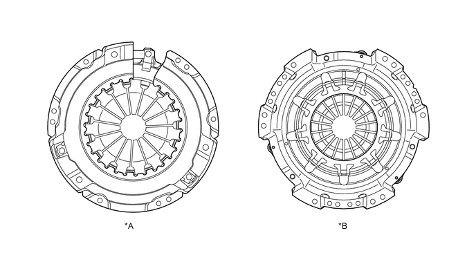
*A TMT Made Models *B TSAM Made Models Figure 2. Models with 2TR-FE Engine
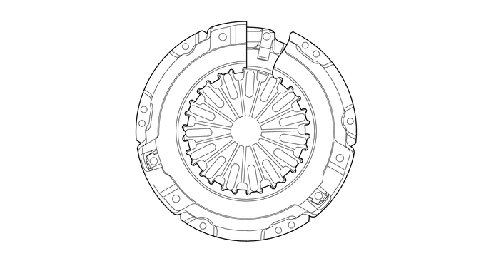
Figure 3. Models with 1GD-FTV Low Version or 2GD-FTV Low Version Engine.
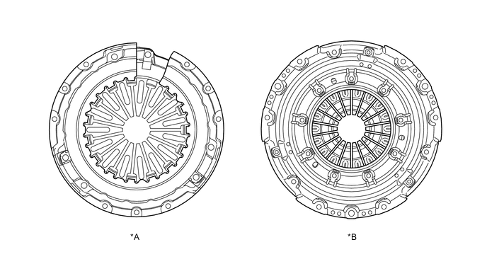
*A TMT Made Models *B TSAM Made Models Figure 4. Models with 1GD-FTV High Version or 2GD-FTV High Version Engine
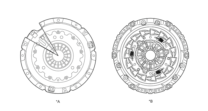
*A TMT Made Models *B TSAM Made Models Figure 5. Models with 2KD-FTV Low Version or 5L-E Engine
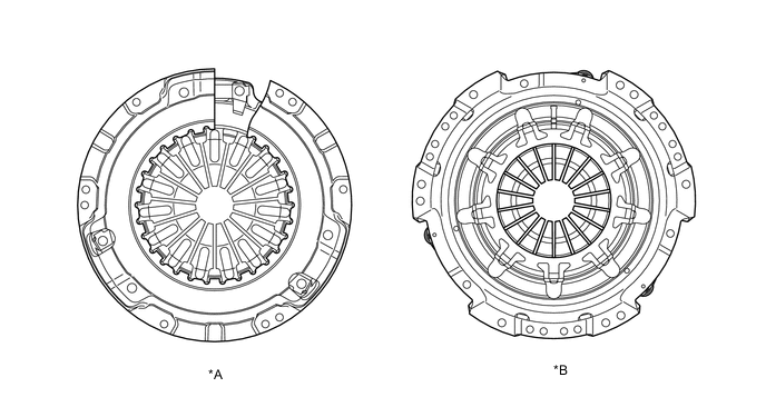
*A TMT Made Models *B TSAM Made Models
-
Low-peak Effort Clutch Type Clutch Cover
-
When the clutch disc is worn, the low-peak effort clutch type clutch cover uses the assist load of the clutch thrust cone spring to restrain increases in the effort required by the driver to depress the clutch pedal, which occur due to changes in the clutch diaphragm spring posture.
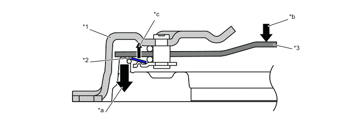
*1 Clutch Cover *2 Clutch Thrust Cone Spring *3 Diaphragm Spring - - *a Diaphragm Load *b Clutch Off Load *c Assistance Load of Clutch Thrust Cone Spring - -
-
-
Self-adjusting Type Clutch Cover
-
The self-adjusting type clutch cover consists of the diaphragm spring, sensor spring, adjust ring, coil spring and pressure plate.
-
When the clutch disc wears, the pressure plate will move in the direction shown by arrow A. The height of the tip of the diaphragm spring will also increase in the direction shown by arrow B, resulting in a change in the diaphragm spring posture. This will increase the installed load of the diaphragm spring applied to the sensor spring.
-
When the installed load becomes excessive, the sensor spring will deform.
-
The clearance between the diaphragm spring and adjust ring will increase due to the deformation of the sensor spring.
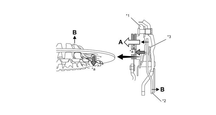
*1 Pressure Plate *2 Diaphragm Spring *3 Adjust Ring - - *a Installed load applied to the sensor spring - - -
However, the coil spring of the clutch cover will rotate the adjust ring, eliminating this clearance.
-
The diaphragm spring posture will be maintained by this mechanism, ensuring a constant pedal effort.
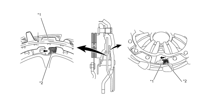
*1 Sensor Spring *2 Coil Spring
-
-
-