BRAKE CONTROL SYSTEM
-
OPERATION
-
Normal Brake Operation (with Regenerative Braking Cooperative Control)
-
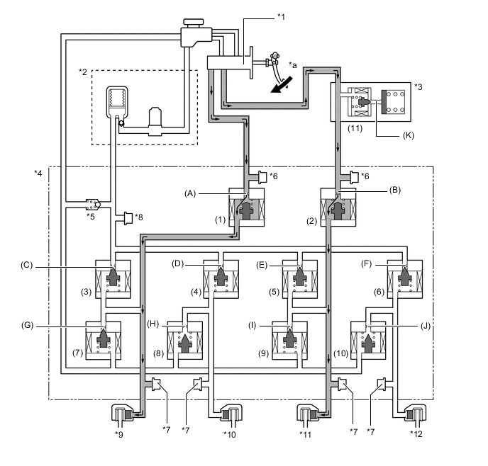
During normal braking, the master cylinder cut solenoid valves are closed and the fluid pressure circuits to the wheel cylinders remain independent. Accordingly, the fluid pressure generated by the brake master cylinder sub-assembly will not directly cause the wheel cylinders to actuate.
-
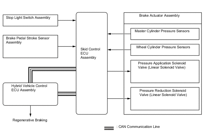
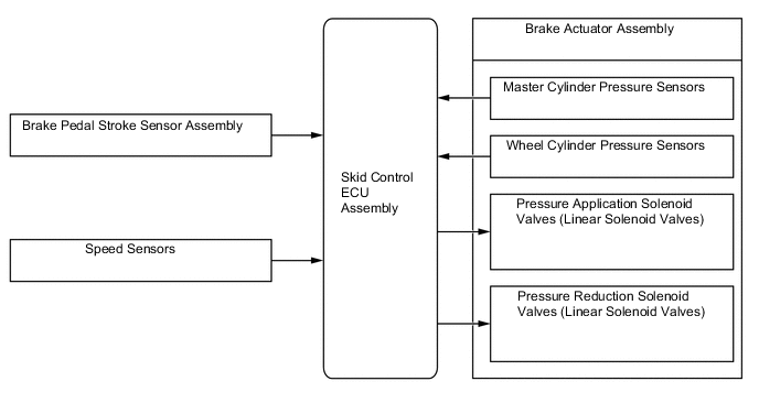
The skid control ECU assembly calculates the braking force required by the driver in accordance with the signals received from the master cylinder pressure sensors and the brake pedal stroke sensor assembly.
-
Then, the skid control ECU assembly calculates the ECU request regenerative brake force value out of the required brake force and transmits this calculated value to the hybrid vehicle control ECU assembly. Upon receiving the value, the hybrid vehicle control ECU assembly generates a regenerative brake force.
-
At the same time, the hybrid vehicle control ECU assembly transmits the actual regenerative brake force value (regenerative braking execution value) to the skid control ECU assembly. The skid control ECU assembly controls the solenoid valves in order to cause the hydraulic brake system to generate a brake force which is obtained by subtracting the regenerative braking execution value from the brake force value required by the driver.
-
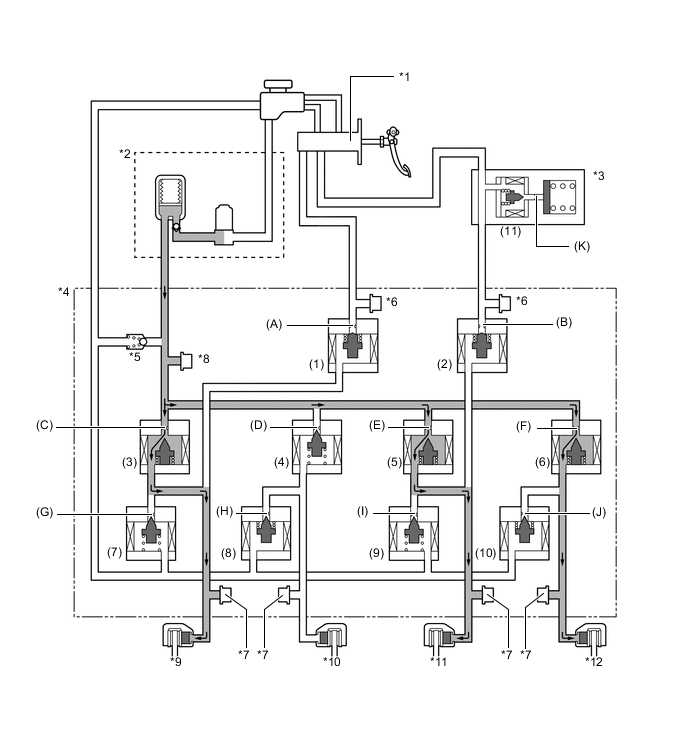
The skid control ECU assembly calculates the target wheel cylinder pressure (equivalent to the brake force required by the driver) in accordance with the signals received from the master cylinder pressure sensor and the brake pedal stroke sensor assembly.
-
The skid control ECU assembly compares the wheel cylinder pressure sensor signal and the target wheel cylinder pressure. If wheel cylinder pressure is lower than the target, the skid control ECU assembly boosts the pressure using the brake actuator assembly.
-
Accordingly, the fluid pressure in the accumulator is fed into the wheel cylinder. Moreover, this operation is the same when the hydraulic brake force must be increased in order to perform cooperative control in accordance with changes in the regenerative braking force.
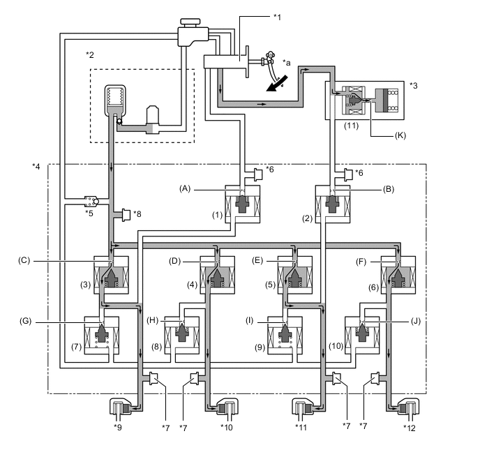
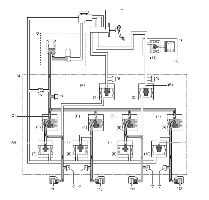
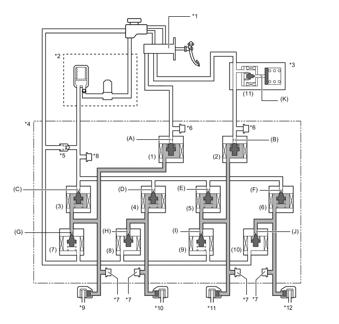
*1 Brake Master Cylinder Sub-assembly *2 Brake Booster Pump Assembly
-
Accumulator
-
Pump
*3 Brake Stroke Simulator Cylinder Sub-assembly *4 Brake Actuator Assembly *5 Relief Valve *6 Master Cylinder Pressure Sensor *7 Wheel Cylinder Pressure Sensor *8 Accumulator Pressure Sensor *9 Front Brake Caliper (Right Side) *10 Rear Brake Caliper (Left Side) *11 Front Brake Caliper (Left Side) *12 Rear Brake Caliper (Right Side) *a Increasing - - -
-
Each valve operates as shown below:
Item Normal Braking Increase Mode (1), (2) Master Cylinder Cut Solenoid Valve ON (Closed) Port: (A), (B) (3), (4), (5), (6) Pressure Application Valve (Linear Type) ON* Port: (C), (D), (E), (F) (7), (9) Pressure Reduction Valve (Linear Type) OFF (Closed) Port: (G), (I) (8), (10) Pressure Reduction Valve (Linear Type) ON (Closed) Port: (H), (J) (11) Stroke Simulator Cut Solenoid Valve ON (Open) Port: (K) *: The solenoid valve constantly regulates the amount of opening of the port in order to control the fluid pressure.
-
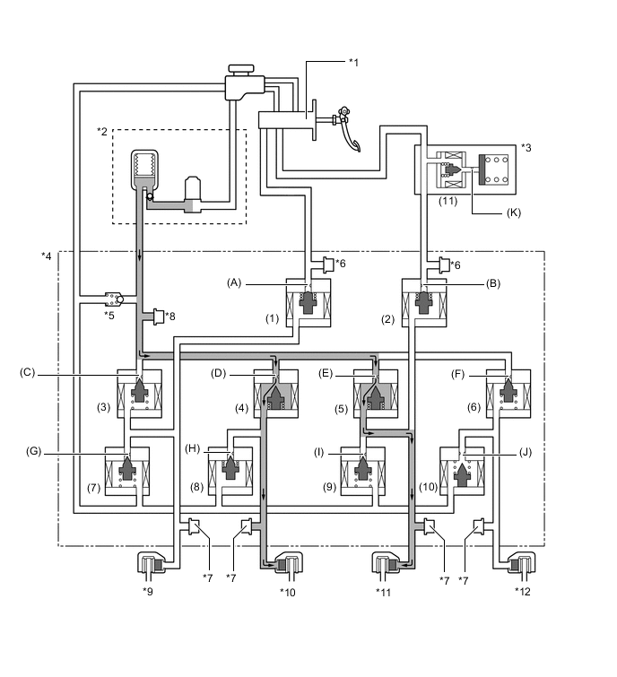
The skid control ECU assembly calculates the target wheel cylinder pressure (equivalent to the brake force required by the driver) in accordance with the signals received from the master cylinder pressure sensor and the brake pedal stroke sensor assembly.
-
The skid control ECU assembly compares the wheel cylinder pressure signal with the target wheel cylinder pressure. If they are equal, the skid control ECU assembly controls the brake actuator assembly in the hold state.
-
Accordingly, the wheel cylinder will be held at a constant pressure.
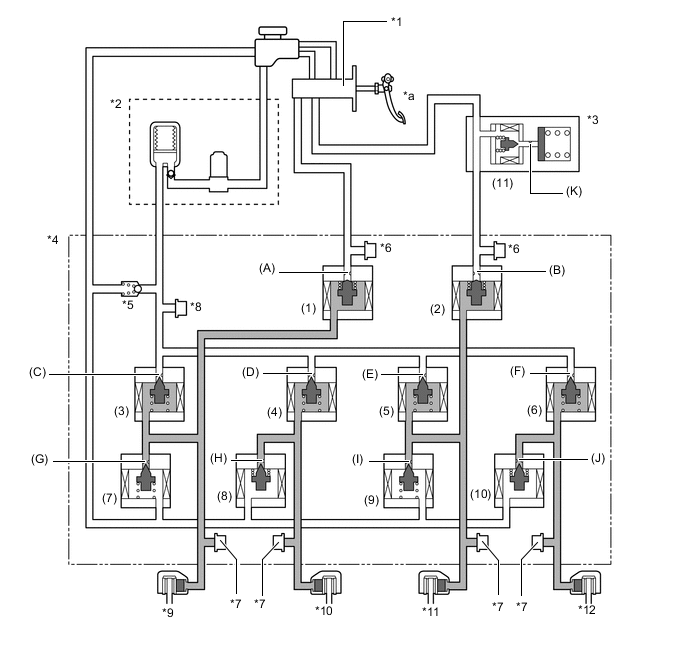
*1 Brake Master Cylinder Sub-assembly *2 Brake Booster Pump Assembly
-
Accumulator
-
Pump
*3 Brake Stroke Simulator Cylinder Sub-assembly *4 Brake Actuator Assembly *5 Relief Valve *6 Master Cylinder Pressure Sensor *7 Wheel Cylinder Pressure Sensor *8 Accumulator Pressure Sensor *9 Front Brake Caliper (Right Side) *10 Rear Brake Caliper (Left Side) *11 Front Brake Caliper (Left Side) *12 Rear Brake Caliper (Right Side) *a Hold - - -
-
Each valve operates as shown below:
Item Normal Braking Holding Mode (1), (2) Master Cylinder Cut Solenoid Valve ON (Closed) Port: (A), (B) (3), (4), (5), (6) Pressure Application Valve (Linear Type) OFF (Closed) Port: (C), (D), (E), (F) (7), (9) Pressure Reduction Valve (Linear Type) OFF (Closed) Port: (G), (I) (8), (10) Pressure Reduction Valve (Linear Type) ON (Closed) Port: (H), (J) (11) Stroke Simulator Cut Solenoid Valve ON (Open) Port: (K) -
The skid control ECU assembly calculates the target wheel cylinder pressure (equivalent to the brake force required by the driver) in accordance with the signals received from the master cylinder pressure sensor and the brake pedal stroke sensor assembly.
-
The skid control ECU assembly compares the wheel cylinder pressure signal with the target wheel cylinder pressure. If wheel cylinder pressure is higher than the target, the skid control ECU assembly reduces the pressure using the brake actuator assembly.
-
Accordingly, the pressure in the wheel cylinder decreases.
-
Moreover, this operation is the same when the hydraulic brake force must be decreased in order to perform cooperative control in accordance with changes in the regenerative braking force.
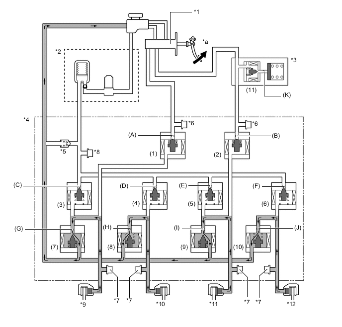
*1 Brake Master Cylinder Sub-assembly *2 Brake Booster Pump Assembly
-
Accumulator
-
Pump
*3 Brake Stroke Simulator Cylinder Sub-assembly *4 Brake Actuator Assembly *5 Relief Valve *6 Master Cylinder Pressure Sensor *7 Wheel Cylinder Pressure Sensor *8 Accumulator Pressure Sensor *9 Front Brake Caliper (Right Side) *10 Rear Brake Caliper (Left Side) *11 Front Brake Caliper (Left Side) *12 Rear Brake Caliper (Right Side) *a Reducing - - -
-
Each valve operates as shown below:
Item Normal Braking Reduction Mode (1), (2) Master Cylinder Cut Solenoid Valve ON (Closed) Port: (A), (B) (3), (4), (5), (6) Pressure Application Valve (Linear Type) OFF (Closed) Port: (C), (D), (E), (F) (7), (9) Pressure Reduction Valve (Linear Type) ON* Port: (G), (I) (8), (10) Pressure Reduction Valve (Linear Type) ON* Port: (H), (J) (11) Stroke Simulator Cut Solenoid Valve ON (Open) Port: (K) *: The solenoid valve constantly regulates the amount of opening of the port in order to control the fluid pressure.
-
-
Electronically Controlled Brake System Stops or During Power Supply Malfunction
-
If the electronically controlled brake system stops or no accumulator pressure is supplied due to some malfunction, the skid control ECU assembly operates the fail-safe function.
-
This function opens the master cylinder solenoid valve in the brake actuator assembly, in order to secure a fluid passage between the brake master cylinder sub-assembly and the wheel cylinder. Thus, the brakes can be applied by operating only the front wheel cylinders using the fluid pressure generated by the brake master cylinder sub-assembly.
-
At this time, port (K) of the stroke simulator cut solenoid valve closes in order to prevent the fluid pressure generated by the brake master cylinder sub-assembly from being negatively affected by the operation of the stroke simulator.
-
In addition, to inform the driver, the skid control ECU assembly sends a warning signal to the combination meter assembly, in addition to sounding the skid control buzzer assembly.
*1 Brake Master Cylinder Sub-assembly *2 Brake Booster Pump Assembly
-
Accumulator
-
Pump
*3 Brake Stroke Simulator Cylinder Sub-assembly *4 Brake Actuator Assembly *5 Relief Valve *6 Master Cylinder Pressure Sensor *7 Wheel Cylinder Pressure Sensor *8 Accumulator Pressure Sensor *9 Front Brake Caliper (Right Side) *10 Rear Brake Caliper (Left Side) *11 Front Brake Caliper (Left Side) *12 Rear Brake Caliper (Right Side) *a Increasing - - -
-
Each valve operates as shown below:
Item Fail-safe Mode (1), (2) Master Cylinder Cut Solenoid Valve OFF (Open) Port: (A), (B) (3), (4), (5), (6) Pressure Application Valve (Linear Type) OFF (Closed) Port: (C), (D), (E), (F) (7), (9) Pressure Reduction Valve (Linear Type) OFF (Closed) Port: (G), (I) (8), (10) Pressure Reduction Valve (Linear Type) OFF (Open) Port: (H), (J) (11) Stroke Simulator Cut Solenoid Valve OFF (Closed) Port: (K)
-
-
ABS with EBD Operation
-
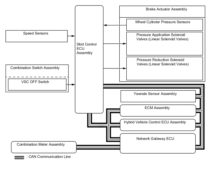
Based on the signals received from the 4 speed sensors, the skid control ECU assembly calculates each wheel speed and deceleration, and checks for wheel slippage. According to wheel slippage, the skid control ECU assembly controls each pressure application valve and pressure reduction valve in order to adjust the fluid pressure of each wheel cylinder in the following 3 modes: pressure reduction, pressure holding, pressure increase modes.
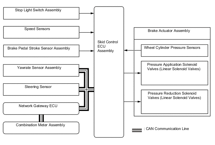
Figure 1. Hydraulic Circuit (Front Brake)
Not Activated Normal Braking - - Activated Increase Mode Holding Mode Reduction Mode Front Brake (1) Pressure Application Solenoid Valve Port (A) On* Off (Closed) Off (Closed) (2) Pressure Reduction Solenoid Valve Port (B) Off (Closed) Off (Closed) On* Wheel Cylinder Pressure Increases Holds Reduces *: The solenoid valve constantly regulates the amount of opening of the port in order to control the fluid pressure.
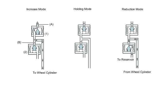
Figure 2. Hydraulic Circuit (Rear Brake)
Not Activated Normal Braking - - Activated Increase Mode Holding Mode Reduction Mode Rear Brake (1) Pressure Application Solenoid Valve Port (A) On* Off (Closed) Off (Closed) (2) Pressure Reduction Solenoid Valve Port (B) On (Closed) On (Closed) On* Wheel Cylinder Pressure Increases Holds Reduces *: The solenoid valve constantly regulates the amount of opening of the port in order to control the fluid pressure.
-
-
Brake Assist Operation
-
In the event of emergency braking, the skid control ECU assembly detects the driver's intention based on the speed of the pressure increase in the brake master cylinder sub-assembly determined by the pressure sensor signals. If the ECU judges the need for additional brake assist, additional fluid pressure is generated by the pump in the actuator and directed to the wheel cylinders.

*1 Brake Master Cylinder Sub-assembly *2 Brake Booster Pump Assembly
-
Accumulator
-
Pump
*3 Brake Stroke Simulator Cylinder Sub-assembly *4 Brake Actuator Assembly *5 Relief Valve *6 Master Cylinder Pressure Sensor *7 Wheel Cylinder Pressure Sensor *8 Accumulator Pressure Sensor *9 Front Brake Caliper (Right Side) *10 Rear Brake Caliper (Left Side) *11 Front Brake Caliper (Left Side) *12 Rear Brake Caliper (Right Side) -
-
Each valve operates as shown below:
Item Normal Braking Increase Mode Brake Assist Activated (1), (2) Master Cylinder Cut Solenoid Valve ON (Closed) ON (Closed) Port: (A), (B) (3), (4), (5), (6) Pressure Application Valve (Linear Type) ON* ON* Port: (C), (D), (E), (F) (7), (9) Pressure Reduction Valve (Linear Type) OFF (Closed) OFF (Closed) Port: (G), (I) (8), (10) Pressure Reduction Valve (Linear Type) ON (Closed) ON (Closed) Port: (H), (J) (11) Stroke Simulator Cut Solenoid Valve ON (Open) ON (Open) Port: (K) *: The solenoid valve constantly regulates the amount of opening of the port in order to control the fluid pressure.
-
-
TRC Operation
-
The fluid pressure generated by the pump is regulated by the pressure application solenoid valve and pressure reduction solenoid valve to the required pressure. Thus, the wheel cylinders of the drive wheels are controlled in the following 3 modes: pressure reduction, pressure holding, and pressure increase modes, to restrain the slippage of the drive wheels.
-
The pressure application valve and the pressure reduction valve are turned on/off according to the ABS operation pattern.
-
The diagram shows the hydraulic circuit in the pressure increase mode when the TRC function is activated.
*1 Brake Master Cylinder Sub-assembly *2 Brake Booster Pump Assembly
-
Accumulator
-
Pump
*3 Brake Stroke Simulator Cylinder Sub-assembly *4 Brake Actuator Assembly *5 Relief Valve *6 Master Cylinder Pressure Sensor *7 Wheel Cylinder Pressure Sensor *8 Accumulator Pressure Sensor *9 Front Brake Caliper (Right Side) *10 Rear Brake Caliper (Left Side) *11 Front Brake Caliper (Left Side) *12 Rear Brake Caliper (Right Side) -
-
Each valve operates as shown below:
Item TRC not Activated TRC Activated Increase Mode Holding Mode Reduction Mode (1), (2) Master Cylinder Cut Solenoid Valve ON (Closed) ON (Closed) ON (Closed) ON (Closed) Port: (A), (B) Front Brake (3), (5) Pressure Application Valve (Linear Type) OFF (Closed) ON* OFF (Closed) OFF (Closed) Port: (C), (E) (7), (9) Pressure Reduction Valve (Linear Type) OFF (Closed) OFF (Closed) OFF (Closed) ON* Port: (G), (I) Wheel Cylinder Pressure - Increase Hold Reduce Rear Brake (4), (6) Pressure Application Valve (Linear Type) OFF (Closed) ON* OFF (Closed) OFF (Closed) Port: (D), (F) (8), (10) Pressure Reduction Valve (Linear Type) OFF (Open) ON (Closed) ON (Closed) ON* Port: (H), (J) Wheel Cylinder Pressure - Increase Hold Reduce (11) Stroke Simulator Cut Solenoid Valve ON (Open) ON (Open) ON (Open) ON (Open) Port: (K) *: The solenoid valve constantly regulates the amount of opening of the port in order to control the fluid pressure.
-
-
VSC and TSC Operation
-
The VSC and TSC function controls the solenoid valves in order to send the fluid pressure stored in the accumulator to the brake wheel cylinders at the respective wheels, through routes that are different from those used during normal braking. Thus, the function operates in the following 3 modes: pressure reduction, pressure holding, and pressure increase. As a result, the tendency of the front wheels or the rear wheels to skid is restrained.
-
In the front wheel skid tendency, this management function applies the brakes of both front wheels and the rear wheel on the inside of the turn. Also, depending on whether the brake is on or off and the condition of the vehicle, there are circumstances in which the brake might not be applied to the wheels even if those wheels are targeted for braking. The diagram below shows the hydraulic circuit in the pressure increase mode, as it restrains the front wheel skid condition while the vehicle makes a right turn.
-
The pressure application valve and the pressure reduction valve are turned on/off according to the ABS operation pattern.
*1 Brake Master Cylinder Sub-assembly *2 Brake Booster Pump Assembly
-
Accumulator
-
Pump
*3 Brake Stroke Simulator Cylinder Sub-assembly *4 Brake Actuator Assembly *5 Relief Valve *6 Master Cylinder Pressure Sensor *7 Wheel Cylinder Pressure Sensor *8 Accumulator Pressure Sensor *9 Front Brake Caliper (Right Side) *10 Rear Brake Caliper (Left Side) *11 Front Brake Caliper (Left Side) *12 Rear Brake Caliper (Right Side) -
-
Each valve operates as shown below:
Item VSC not Activated VSC Activated Increase Mode Holding Mode Reduction Mode (1), (2) Master Cylinder Cut Solenoid Valve ON (Closed) ON (Closed) ON (Closed) ON (Closed) Port: (A), (B) Front Brake (3) Pressure Application Valve (Linear Type) OFF (Closed) ON* OFF (Closed) OFF (Closed) Port: (C) (5) Pressure Application Valve (Linear Type) OFF (Closed) ON* OFF (Closed) OFF (Closed) Port: (E) (7) Pressure Reduction Valve (Linear Type) OFF (Closed) OFF (Closed) OFF (Closed) ON* Port: (G) (9) Pressure Reduction Valve (Linear Type) OFF (Closed) OFF (Closed) OFF (Closed) ON* Port: (I) Wheel Cylinder Pressure Right - Increase Hold Reduce Left Rear Brake (4) Pressure Application Valve (Linear Type) OFF (Closed) OFF (Closed) OFF (Closed) OFF (Closed) Port: (D) (6) Pressure Application Valve (Linear Type) OFF (Closed) ON* OFF (Closed) OFF (Closed) Port: (F) (8) Pressure Reduction Valve (Linear Type) OFF (Open) OFF (Open) OFF (Open) ON* Port: (H) (10) Pressure Reduction Valve (Linear Type) OFF (Open) ON (Closed) ON (Closed) ON* Port: (J) Wheel Cylinder Pressure Right - Increase Hold Reduce Left - - - (11) Stroke Simulator Cut Solenoid Valve ON (Open) ON (Open) ON (Open) ON (Open) Port: (K) *: The solenoid valve constantly regulates the amount of opening of the port in order to control the fluid pressure.
-
In rear wheel skid tendency, this management function applies the brake to the front and rear wheel of the outer circle of the turn. In some cases, the skid control ECU assembly applies the brake to the rear wheels, as necessary. As an example, the diagram below shows the hydraulic circuit in the pressure increase mode, as it restrains the rear wheel skid condition while the vehicle makes a right turn.
-
As in front wheel skid restraint control, the pressure application valve and the pressure reduction valve are turned ON/OFF according to the ABS operating pattern.
*1 Brake Master Cylinder Sub-assembly *2 Brake Booster Pump Assembly
-
Accumulator
-
Pump
*3 Brake Stroke Simulator Cylinder Sub-assembly *4 Brake Actuator Assembly *5 Relief Valve *6 Master Cylinder Pressure Sensor *7 Wheel Cylinder Pressure Sensor *8 Accumulator Pressure Sensor *9 Front Brake Caliper (Right Side) *10 Rear Brake Caliper (Left Side) *11 Front Brake Caliper (Left Side) *12 Rear Brake Caliper (Right Side) -
-
Each valve operates as shown below:
Item VSC not Activated VSC Activated Increase Mode Holding Mode Reduction Mode (1), (2) Master Cylinder Cut Solenoid Valve ON (Closed) ON (Closed) ON (Closed) ON (Closed) Port: (A), (B) Front Brake (3) Pressure Application Valve (Linear Type) OFF (Closed) OFF (Closed) OFF (Closed) OFF (Closed) Port: (C) (5) Pressure Application Valve (Linear Type) OFF (Closed) ON*1 OFF (Closed) OFF (Closed) Port: (E) (7) Pressure Reduction Valve (Linear Type) OFF (Closed) OFF (Closed) OFF (Closed) OFF (Closed) Port: (G) (9) Pressure Reduction Valve (Linear Type) OFF (Closed) OFF (Closed) OFF (Closed) ON*1 Port: (I) Wheel Cylinder Pressure Right - - - - Left - Increase Hold Reduce Rear Brake (4) Pressure Application Valve (Linear Type) OFF (Closed) ON*1 OFF (Closed) OFF (Closed) Port: (D) (6) Pressure Application Valve (Linear Type) OFF (Closed) OFF (Closed)/ON*1, *2 OFF (Closed) OFF (Closed) Port: (F) (8) Pressure Reduction Valve (Linear Type) OFF (Open) ON (Closed) ON (Closed) ON*1 Port: (H) (10) Pressure Reduction Valve (Linear Type) OFF (Open) OFF (Open) OFF (Open)/ON (Closed)*2 OFF (Open)/ON*1, *2 Port: (J) Wheel Cylinder Pressure Right - - - - Left - Increase Hold Reduce (11) Stroke Simulator Cut Solenoid Valve ON (Open) ON (Open) ON (Open) ON (Open) Port: (K) *1: The solenoid valve constantly regulates the amount of opening of the port in order to control the fluid pressure.
*2: In some cases, the skid control ECU assembly applies the brakes of the rear wheels, as necessary.
-
-
Hill-start Assist Control Operation
-
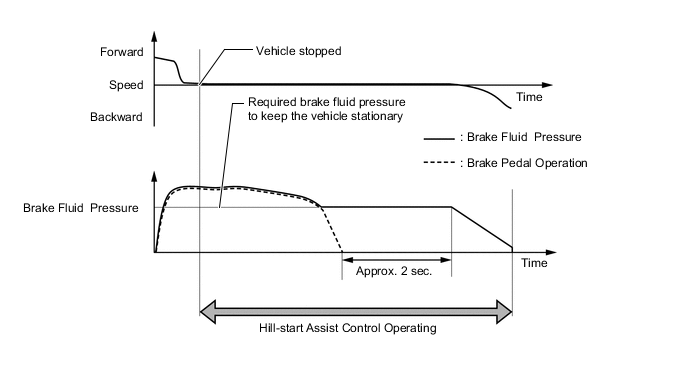
Hill-start Assist Control controls the brakes by maintaining the fluid pressure produced when the brake pedal is depressed.
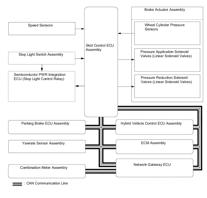
Figure 3. Example of Hill-start Assist Control when Climbing Uphill with Shift Lever in D (Driver Depresses Accelerator Pedal to Start Off after Hill-start Assist Control Operation)
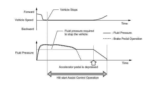
Figure 4. Example of Hill-start Assist Control when Climbing Uphill with Shift Lever in D (Driver Takes No Action after Hill-start Assist Control Operation)
*1 Brake Master Cylinder Sub-assembly *2 Brake Booster Pump Assembly
-
Accumulator
-
Pump
*3 Brake Stroke Simulator Cylinder Sub-assembly *4 Brake Actuator Assembly *5 Relief Valve *6 Master Cylinder Pressure Sensor *7 Wheel Cylinder Pressure Sensor *8 Accumulator Pressure Sensor *9 Front Brake Caliper (Right Side) *10 Rear Brake Caliper (Left Side) *11 Front Brake Caliper (Left Side) *12 Rear Brake Caliper (Right Side) -
-
Each valve operates as shown below:
Item Hill-start Assist Control not Activated Hill-start Assist Control Activated Holding Mode Reduction Mode (1), (2) Master Cylinder Cut Solenoid Valve ON (Closed) ON (Closed) ON (Closed) Port: (A), (B) Front Brake (3) Pressure Application Valve (Linear Type) OFF (Closed) OFF (Closed) OFF (Closed) Port: (C) (5) Pressure Application Valve (Linear Type) OFF (Closed) OFF (Closed) OFF (Closed) Port: (E) (7) Pressure Reduction Valve (Linear Type) OFF (Closed) OFF (Closed) ON (Open) Port: (G) (9) Pressure Reduction Valve (Linear Type) OFF (Closed) OFF (Closed) ON (Open) Port: (I) Rear Brake (4) Pressure Application Valve (Linear Type) OFF (Closed) OFF (Closed) OFF (Closed) Port: (D) (6) Pressure Application Valve (Linear Type) OFF (Closed) OFF (Closed) OFF (Closed) Port: (F) (8) Pressure Reduction Valve (Linear Type) OFF (Open) ON (Closed) OFF (Open) Port: (H) (10) Pressure Reduction Valve (Linear Type) OFF (Open) ON (Closed) OFF (Open) Port: (J) (11) Stroke Simulator Cut Solenoid Valve ON (Open) ON (Open) ON (Open) Port: (K)
-
-
Radar Cruise Control Brake
-
The skid control ECU assembly operates the brakes by receiving a deceleration request signal from the hybrid vehicle control ECU assembly while the dynamic radar cruise control system is being activated. This brake control operates in the same way as the normal brake operation.
-
-
Pre-crash Brake
-
If the driving support ECU assembly determines that the possibility of a collision is high, the ECU sends the pre-crash brake assist request signal to the skid control ECU assembly. Upon receiving the signal, the skid control ECU assembly switches the brake assist to standby mode. When the driver depresses the brake pedal, the skid control ECU assembly operates the brake assist based on the master cylinder pressure sensor.
-
If a collision is unavoidable, the skid control ECU assembly actuates the motor in the power supply portion to apply direct pressure to the wheel cylinders even if the driver does not depress the brake pedal. This brake control operates in the same way as the normal brake operation.
-
-
VSC and Cooperative Control with EPS (Models for General Countries)
-
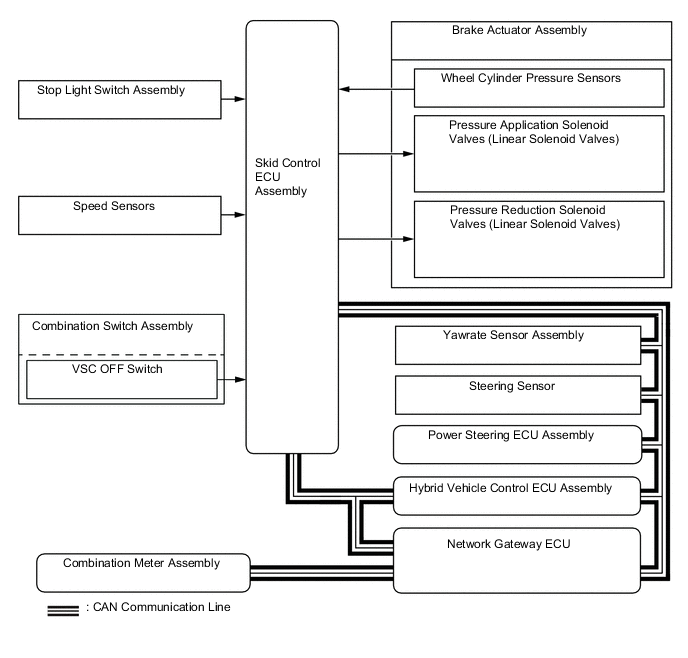
The operation of the solenoid valves under the steering cooperative control is the same as the TRC or VSC operation.
-
-
VSC+ (Models for Europe)
-
The operation of the solenoid valves under the steering cooperative control is the same as the TRC or VSC operation.
-
-
Brake Hold
-
The operation of the solenoid valves under the brake hold is the same as the operation of the hill-start assist control.
-
-