POWER MIRROR CONTROL SYSTEM Reverse Shift-linked Function of Power Mirrors does not Operate
| DTC Code | DTC Name |
|---|---|
| Reverse Shift-linked Function of Power Mirrors does not Operate |
SYSTEM DESCRIPTION
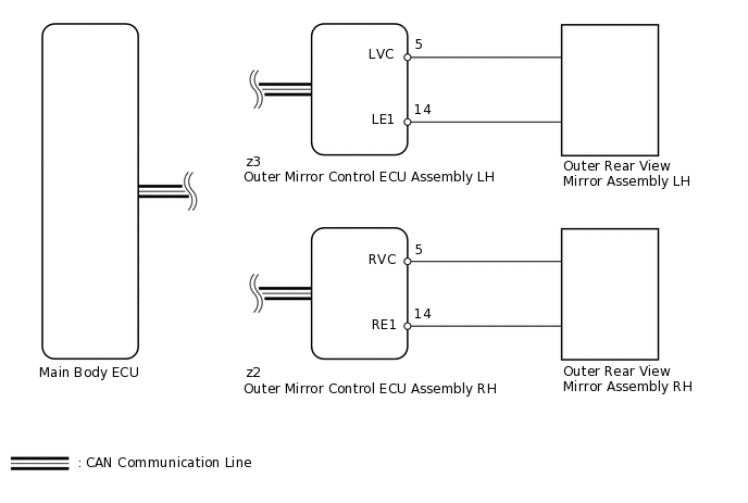
ECM sends the reverse signal to the main body ECU (multiplex network body ECU) via CAN communication. When receiving the reverse signal, the main body ECU (multiplex network body ECU) sends the reverse request signal to each outer mirror control ECU assembly. Each outer mirror control ECU assembly then performs control in response to the reverse signal.
WIRING DIAGRAM
CAUTION / NOTICE / HINT
The reverse shift-linked function will not activate when the mirror select switch is in the neutral position (off).
PROCEDURE
CHECK CAN COMMUNICATION SYSTEM
Check if a CAN communication DTC is output.
Result
Result
Proceed to
DTC is not output
A
DTC is output
B
CHECK POWER MIRROR CONTROL FUNCTION (ELECTRICAL REMOTE CONTROL MIRROR FUNCTION)
Check the electrical remote control mirror function.
OK
Electrical remote control mirror function is normal.
Result
Result
OK
NG
CHECK COMBINATION METER ASSEMBLY
Check if the shift position indicator light in the combination meter assembly operates normally.
OK
Shift position indicator light indicates actual shift position correctly.
Result
Result
OK
NG
READ VALUE USING INTELLIGENT TESTER (MIRROR POSITION SENSOR)
Using the intelligent tester, read the Data List.
Body Electrical > Mirror L > Data List
Tester Display
Measurement Item
Range
Normal Condition
Diagnostic Note
Mirror Vertical Sensor Vol
Vertical mirror position
MIN: 0, MAX: 4.98 V
Within range from 0 to 4.98 V
-
Mirror Horizontal Sensor Vol
Horizontal mirror position
MIN: 0, MAX: 4.98 V
Within range from 0 to 4.98 V
-
Body Electrical > Mirror R > Data List
Tester Display
Measurement Item
Range
Normal Condition
Diagnostic Note
Mirror Vertical Sensor Vol
Vertical mirror position
MIN: 0, MAX: 4.98 V
Within range from 0 to 4.98 V
-
Mirror Horizontal Sensor Vol
Horizontal mirror position
MIN: 0, MAX: 4.98 V
Within range from 0 to 4.98 V
-
OK
Output voltage is as shown in table above.
Result
Result
Proceed to
Driver side mirror does not operate normally
A
Driver side mirror operates normally
B
Passenger side mirror does not operate normally
C
Passenger side mirror operates normally
D
C CHECK OUTER MIRROR CONTROL ECU ASSEMBLY RHClick here
CHECK OUTER MIRROR CONTROL ECU ASSEMBLY LH
-
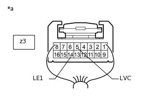
*a
Component with harness connected
(Outer Mirror Control ECU Assembly LH)
Remove the outer mirror control ECU assembly LH with its connectors still connected.
Measure the voltage according to the value(s) in the table below.
Standard Voltage
Tester Connection
Condition
Specified Condition
z3-5 (LVC) - z3-14 (LE1)
Engine switch on (IG)
4.7 to 5.3 V
Measure the resistance according to the value(s) in the table below.
Standard Resistance
Tester Connection
Condition
Specified Condition
z3-14 (LE1) - Body ground
Always
Below 1 Ω
Result
Result
OK
NG
-
CHECK OUTER MIRROR CONTROL ECU ASSEMBLY RH
-
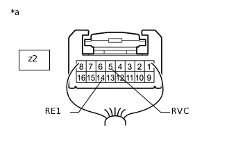
*a
Component with harness connected
(Outer Mirror Control ECU Assembly RH)
Remove the outer mirror control ECU assembly RH with its connectors still connected.
Measure the voltage according to the value(s) in the table below.
Standard Voltage
Tester Connection
Condition
Specified Condition
z2-5 (RVC) - z2-14 (RE1)
Engine switch on (IG)
4.7 to 5.3 V
Measure the resistance according to the value(s) in the table below.
Standard Resistance
Tester Connection
Condition
Specified Condition
z2-14 (RE1) - Body ground
Always
Below 1 Ω
Resule
Resule
OK
NG
-