LANE DEPARTURE ALERT SYSTEM, Diagnostic DTC:C1AA7
| DTC Code | DTC Name |
|---|---|
| C1AA7 | Skid Control Buzzer Circuit |
DESCRIPTION
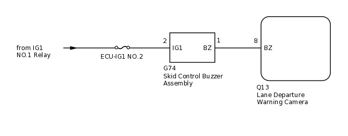
The lane departure warning camera sends a buzzer request signal to the skid control buzzer assembly to sound the buzzer. When the lane departure warning camera detects a malfunction in the skid control buzzer circuit, the lane departure warning camera stores DTC C1AA7.
DTC No. |
Detection Item |
DTC Detection Condition |
Trouble Area |
|---|---|---|---|
C1AA7 |
Skid Control Buzzer Circuit |
|
|
WIRING DIAGRAM
CAUTION / NOTICE / HINT
When the lane departure warning camera is replaced with a new one, adjustment of the lane departure warning camera beam axis must be performed.
Inspect the fuses for circuits related to this system before performing the following inspection procedure.
PROCEDURE
CHECK HARNESS AND CONNECTOR (SKID CONTROL BUZZER ASSEMBLY - LANE DEPARTURE WARNING CAMERA AND BATTERY)
Disconnect the G74 skid control buzzer assembly connector.
Disconnect the Q13 lane departure warning camera connector.
Measure the voltage according to the value(s) in the table below.
Standard Voltage
Tester Connection
Switch Condition
Specified Condition
G74-2 (IG1) - Body ground
Ignition switch ON
11 to 14 V
Ignition switch off
Below 1 V
Measure the resistance according to the value(s) in the table below.
Standard Resistance
Tester Connection
Condition
Specified Condition
G74-1 (BZ) - Q13-8 (BZ)
Always
Below 1 Ω
G74-1 (BZ) - Body ground
Always
10 kΩ or higher
Result
Proceed to
OK
NG
NG REPAIR OR REPLACE HARNESS OR CONNECTOR
INSPECT SKID CONTROL BUZZER ASSEMBLY
Remove the skid control buzzer assembly.
for LHD:
for RHD:
Inspect the skid control buzzer assembly.
for LHD:
for RHD:
Result
Proceed to
OK
NG