INTELLIGENT PARKING ASSIST SYSTEM
-
FUNCTION OF MAIN COMPONENTS
-
The main components in the intelligent parking assist system have the following functions:
Component Function No. 1 Ultrasonic Sensor LH
No. 1 Ultrasonic Sensor RH
Detects the distance between the driven vehicle and the parked vehicle, and outputs it to the parking assist ECU. Parking Assist ECU
-
Sends video signals, which contain a composite view of the area behind the vehicle taken with the rear television camera assembly and the parking guide lines and target frame, to the navigation receiver assembly. Furthermore, it performs overall control of the system based on signals received from ECUs.
-
Determines if enough parking space is available based on the signals from the ultrasonic sensors.
-
Sets the display language for parking assist according to the language setup information from the navigation receiver assembly.
-
Provides power from the headlight leveling ECU assembly to the rear height control sensor sub-assembly RH.*1
-
Provides power to the rear height control sensor sub-assembly RH.*2
Rear Television Camera Assembly Mounted on the back door to transmit the rear view of the vehicle to the parking assist ECU. Navigation Receiver Assembly Receives image signals from the parking assist ECU and displays the image of the area behind the vehicle on the multi-display. Parking Assist Pre Support Switch Assembly Turns the pre-support function on/off and switches between parking assist mode (perpendicular parking) and parallel parking assist mode. Spiral Cable with Sensor Sub-assembly
- Steering Angle Sensor
Detects the angle of the steering wheel, and sends a signal to the parking assist ECU via the skid control ECU. Power Management Control ECU
-
Sends vehicle condition signals such as the accelerator pedal angle signal and shift position signal to the parking assist ECU.
-
Sends a reverse signal to the No. 1 integration relay.
-
Receives the creep force increase request signal from the parking assist ECU and increases motive force from MG2.
Main Body ECU (Multiplex Network Body ECU) Sends the parking brake signal and back door courtesy switch signal to the parking assist ECU. Brake Booster with Master Cylinder Assembly
- Skid Control ECU
Sends the wheel speed signal to the parking assist ECU. Power Steering ECU Assembly
-
Performs steering control upon receiving signals such as the steering control signal from the parking assist ECU.
-
Sends vehicle condition signals such as the EPS fail-safe signal and steering control status signal to the parking assist ECU.
No. 1 Integration Relay Sends the reverse signal from the power management control ECU to the navigation receiver assembly. Shift Lock Control Unit Assembly Sends a reverse signal to the power management control ECU. Rear Height Control Sensor Sub-assembly RH Sends changes in vehicle height received from the rear height control sensor sub-assembly RH to the parking assist ECU. Headlight Leveling ECU Assembly*1 Provides power to the rear height control sensor sub-assembly RH via the parking assist ECU. Air Conditioning Amplifier Assembly Sends outside temperatures received from the outside temperature sensor (thermistor assembly) to the parking assist ECU. Front No. 1 Speaker Assembly
Front No. 2 Speaker Assembly
Outputs voice guidance for the respective mode, in accordance with the voice signals received from the parking assist ECU via the navigation receiver assembly.
-
*1: Models with LED headlights
-
*2: Models without LED headlights
-
-
-
OPERATING CONDITION
-
The operation condition of each function of the intelligent parking assist system varies as follows:
Function Operating Condition Pre-support Function
-
Power switch is on (READY).
-
Neutral (N), drive (D) or brake (B) is selected.
-
Back door is closed.
-
Vehicle speed is approximately 15 km/h (9 mph) or less.
-
Parking assist pre support switch assembly is on.
Rear Display Mode
-
Power switch is on (READY).
-
Assist mode switch is ON.
-
Back door is closed.
-
Reverse (R) is selected.
Parking Assist Mode (Perpendicular Parking) or Parallel Parking Assist Mode
-
Power switch is on (READY).
-
Assist mode switch is ON.
-
Back door is closed.
-
Reverse (R) is selected.
Estimated Guide Line Mode, Parking Guide Line Mode or Guide Line Deletion Mode
-
Power switch is on (READY).
-
Assist mode switch is OFF.
-
Back door is closed.
-
Reverse (R) is selected.
-
-
-
FUNCTION
-
Area Displayed on Screen
-
On the display, objects on the right of the vehicle appear on the right side of the display panel, and objects on the left of the vehicle appear on the left side of the display panel.
-
The television camera uses a wide-angle lens. The perceived distance from images that appear on the screen differs from the actual distance.
Note
The area displayed on the screen may vary according to vehicle status or road conditions. The area covered by the rear television camera assembly is limited. The rear television camera assembly does not show objects close to either corner of the bumper or show the area under the bumper.
-
-
Display Function (Display Modes)
Assist Mode Switch Mode Outline - Rear Display Mode Displays an image of the area behind the vehicle taken by the rear television camera assembly. ON Parking Assist Mode
(Perpendicular Parking)
Displays the target parking frame on the navigation display. Parallel Parking Assist Mode OFF Estimated Guide Line Mode Displays the guide lines on the navigation display. Parking Guide Line Mode Guide Line Deletion Mod -
Rear Display Mode
-
In rear display mode, an image of the area behind the vehicle is displayed on the navigation receiver assembly to assist the driver.
-
During rear display mode (assist mode select switch is on), the intelligent parking guidance mode can be selected.
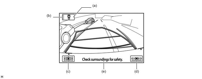
Item Description of Display (a) Assist Mode Select Switch Disables and enables intelligent parking guidance mode. (b) Indicator Shows the assist mode state.
-
Illuminated: Intelligent parking guidance mode
-
Not illuminated: Rear view monitor mode
(c) Parking Assist Mode Switch These switches appear on the screen when reverse (R) is selected. The system transfers to parking assist mode (perpendicular parking) or parallel parking assist mode when the driver touches the respective switch. (d) Parallel Parking Assist Mode Switch (e) Warning Message Display Area Area where warning messages are displayed. -
-
Rear display mode (assist mode select switch is off) has 3 modes: estimated guide line mode (B), parking guide line mode (C) and guide line deletion mode (D).
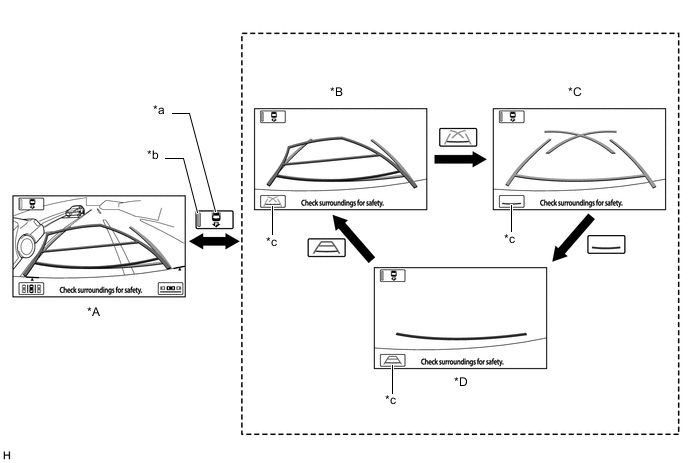
Text in Illustration *A Rear Display Mode *B Estimated Guide Line Mode *C Parking Guide Line Mode *D Guide Line Deletion Mode *a Assist Mode Switch *b Indicator *c Line Mode Button - -
-
-
Parking Assist Mode (Perpendicular Parking)
-
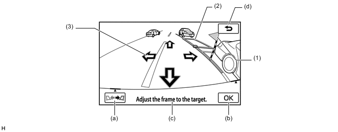
When the system operates in parking assist mode (perpendicular parking), it displays a composite view of the area behind the vehicle and the target parking frame that are necessary for the perpendicular parking. In addition, it assists the driver's steering maneuver.
-
A direct touch function is used. This function allows the driver to set a target parking position by touching the foremost corner of the target parking frame.
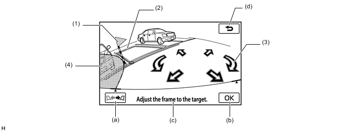
Item Description of Display (1) Warning Flag Displays the approximate position at which the vehicle will come in contact with an obstacle, while a target parking position is being set. Thus, a target parking position should be set at a position that does not overlap with an obstacle. (2) Target Parking Frame
(Blue or Red)
Displays the present target parking position.
Blue: The target parking position is OK and can be confirmed.
Red: The target parking position is not appropriate and cannot be confirmed.
(3) Arrows Switch Moves the target parking position in the direction of the arrow that is touched. (4) Inaccessible Area Displays the area inaccessible for parking that is judged based on the steering angle state. (a) Switch Orientation Switch Switches the right-left orientation of the target parking position. (b) OK Switch Confirms the target parking position. (c) Warning Message Display Area Area where warning messages are displayed. (d) Return Switch Returns the screen to rear display mode.
-
-
Parallel Parking Assist Mode
-
When the system operates in parallel parking assist mode, it displays a composite view of the area behind the vehicle and the target parking frame that are necessary for parallel parking. In addition, it assists the driver's steering maneuver.
-
A direct touch function is used. This function allows the driver to set a target parking position by touching the foremost corner of the target parking frame.
Item Description of Display (1) Warning Flag Displays the approximate position at which the vehicle will come in contact with an obstacle, while a target parking position is being set. Thus, a target parking position should be set at a position that does not overlap with an obstacle. (2) Target Parking Frame
(Blue or Red)
Displays the present target parking position.
Blue: The target parking position is OK.
Red: The target parking position is not OK.
(3) Arrow Switch Moves the target parking position in the direction of the arrow that is touched. (a) Switch Orientation Switch Switches the right-left orientation of the target parking position. (b) OK Switch Confirms the target parking position. (c) Warning Message Display Area Area where warning messages are displayed. (d) Return Switch Returns the screen to rear display mode.
-
-
Estimated Guide Line Mode
-
A description of the estimated guide line display is provided in the following diagram.
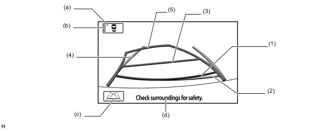
Item Description (1) Distance Guide Line (Red) Moves together with estimated guide lines in sync with the steering wheel. The center of the line indicates a position on the ground approximately 0.5 m (1.6 ft.) behind the rear bumper. (2) Distance Guide Line (Blue) Indicates a position on the ground approximately 0.5 m (1.6 ft.) behind the rear bumper. (3) Distance Guide Line (Yellow) Indicates a position on the ground approximately 1.0 m (3.3 ft.) behind the rear bumper. (4) Vehicle Width Extension Guide Line (Blue) Indicates the estimated vehicle width. (5) Estimated Guide Line (Yellow) Moves in sync with the steering wheel to indicate the estimated reverse course of the vehicle. (a) Assist Mode Switch Switches assist mode between rear view monitor mode and advanced parking guidance mode. (b) Indicator Shows the assist mode state.
-
Illuminated: Advanced parking guidance mode
-
Not illuminated: Rear view monitor mode
(c) Line Mode Button Pressing this button changes the rear view monitor mode. (d) Warning Message Display Area Area where warning messages are displayed. -
-
-
Parking Guide Line Mode
-
A description of the parking guide line mode display is provided in the following diagram.
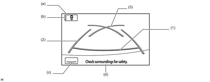
Item Description (1) Distance Guide Line (Red) Indicates a position on the ground approximately 0.5 m (1.6 ft.) behind the rear bumper. (2) Vehicle Width Extension Guide Line (Blue) Indicates the estimated vehicle width. (3) Parking Assist Guide Line (Blue) Indicates the path the vehicle will follow if the driver turns the steering wheel fully. (a) Assist Mode Switch Switches the assist mode between rear view monitor mode and advanced parking guidance mode. (b) Indicator Shows the assist mode state.
-
Illuminated: Advanced parking guidance mode
-
Not illuminated: Rear view monitor mode
(c) Line Mode Button Pressing this button changes the rear view monitor mode. (d) Warning Message Display Area Area where warning messages are displayed. -
-
-
Guide Line Deletion Mode
-
A description of the guide line deletion mode display is provided in the following diagram.
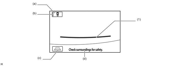
Item Description (1) Distance Guide Line (Red) Indicates a position on the ground approximately 0.5 m (1.6 ft.) behind the rear bumper. (a) Assist Mode Switch Switches the assist mode between rear view monitor mode and advanced parking guidance mode. (b) Indicator Shows the assist mode state.
-
Illuminated: Advanced parking guidance mode
-
Not illuminated: Rear view monitor mode
(c) Line Mode Button Pressing this button changes the rear view monitor mode. (d) Warning Message Display Area Area where warning messages are displayed. -
-
-
Pre-support Function
-
When the No. 1 ultrasonic sensor detects a space where the vehicle can be parked and the driver operates the parking assist pre support switch assembly, the screen display and voice guidance direct the driver to the back up start position (parking assist start position) in both modes; parking assist (perpendicular parking) mode and parallel parking assist mode. In parking assist (perpendicular parking) mode the guidance gives the timing for turning the steering wheel, and in parallel parking assist mode the guidance notifies the driver of the stop position.
-
-
Visual Servo Function
-
When parking assist (perpendicular parking) mode is operating, the lines of the parking space are continuously recognized in the image to ensure that the vehicle follows the lines of the parking space. When the vehicle approaches the lines of the parking space and the visual recognition accuracy increases, the target parking position is corrected.
-
-
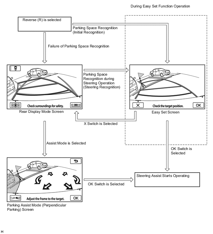
Easy Set Function
-
If the intelligent parking assist system recognizes the lines of the parking space when the shift lever is moved to R, the easy set screen will appear (initial recognition). This enables the driver to omit the operation of setting the targeting parking position, shortening the time required until assist starts.
Tech Tips
In a situation where the easy set function cannot operate, such as when parallel parking, a parking place with no parking lines or a place where parking line recognition is difficult, normal setting of the target parking place is available using the parking assist mode switch or parallel parking assist mode switch.
-
If the parking lines are not detected initially, steering toward the target parking space may enable the intelligent parking assist system to detect the lines. When the system judges that the assist route can be set, the easy set screen appears (steering recognition). When the easy set screen is displayed due to steering recognition, it is possible to start assistance without returning the steering wheel to the neutral position.
-
Under the following conditions, the easy set function may not operate because parking lines (white) cannot be recognized:
-
Parking spaces without parking lines (parking spaces marked with rope, blocks etc.)
-
Unclear, dirty or chipped parking lines
-
Parking spaces with lines that are difficult to differentiate from the road surface due to a small brightness difference (such as yellow lines on concrete)
-
-
Under the following conditions, the system may recognize the target parking position improperly.
-
Parking spaces with interfering lines or objects (lines other than parking lines or obstacles such as poles)
-
Parking spaces on a slope
-
If detection of the space is affected by nearby vehicles (such as a shadow, grill or side step of a nearby vehicle)
-
Unclear, dirty or chipped parking lines
-
Parking spaces with lines that are difficult to differentiate from the road surface due to a small brightness difference (such as yellow lines on concrete)
-
-
Under the following conditions, the easy set function cannot operate.
-
When the assist mode switch is not selected
-
During the screen transition from the pre-support function
-
While parallel parking
-
-
-
Warning Message Function
-
A warning message appears at the bottom, side or center of the screen under the following conditions. The warning message appears in the same language that has been selected by using the multi-display.
Messages Appearing at Bottom of Screen Warning Message Outline Check surroundings for safety. This message always appears during system operation. System initializing. Appears when the steering wheel is operated while the auxiliary battery terminal (-) is disconnected and then the terminal is reconnected. Guidance unavailable. This message appears if there is a malfunction in this system. Stop vehicle by using foot brake. This message and the "Check surroundings for safety." message appear alternately when the driver is backing up the vehicle and attempting to park it in the target parking position. Messages Appearing at the Center of Screen Warning Message Outline System not ready. This message appears if the system is not initialized. Check IPA system. Have your vehicle checked by a dealer. This message appears if there is a malfunction in a system component. Assist has been cancelled. This message appears as a result of the operation of the steering wheel or accelerator pedal while the system is operating in parking assist mode. Speed is too fast. This message appears if the backing speed is too fast while the system is operating in parking assist mode. Parking position has not been set. This message appears as a result of the driver starting to back up without touching the OK button after the target parking position has turned blue. Release parking brake. This message appears as a result of the driver attempting to operate the system without releasing the parking brake. Depress the brake pedal. This message appears as a result of the driver touching the OK button while the brake hold system is operating. Accelerator pedal has been engaged. This message appears if the accelerator pedal is depressed while the system is operating in parking assist mode. Clean Park Sonar. This message appears if the No. 1 ultrasonic sensor is frozen or dirty. Use on flat surface. This message appears if the vehicle starts to roll downhill or if the vehicle fails to move uphill when the brake pedal is released. System cannot assist under current conditions. This message appears if the system is operating in parking assist mode and a tire is worn or the tire pressure is lower than the specified value. IPA not available now. This warning is displayed when an attempt is made to operate the intelligent parking assist system in an environment where the system cannot be operated such as on a steep incline. Too much force applied to the steering wheel. This message appears if the steering wheel is held too tightly when the system is operated in the parking assist mode. Steering position is not neutral. Turn the steering wheel to the LEFT (or RIGHT). This message appears if the steering wheel is not centered.
-
-
Calibration Following Parts Replacement
-
The items listed below must always be adjusted whenever one of the following conditions occurs. For details, refer to the Repair Manual.
Adjustment Items Condition Neutral steering point in memory After spiral cable with sensor sub-assembly is removed and installed or after connector is disconnected and reconnected, "System initializing." is displayed. Steering angle setting
-
After spiral cable with sensor sub-assembly is removed and installed or after connector is disconnected and reconnected, "System initializing." is displayed.
-
Spiral cable with sensor sub-assembly replacement.
Camera optical axis adjustment
-
Vehicle height has changed due to replacement of suspension parts or tires.
-
The installation angle of the rear television camera assembly has changed.
-
When the rear height control sensor sub-assembly RH is misaligned such as after disassembly and installation or after replacement.
Installation position adjustment of the height control sensor
-
Vehicle height has changed due to replacement of suspension parts or tires.
-
The installation angle of the rear television camera assembly has changed.
-
When the rear height control sensor sub-assembly RH is misaligned such as after disassembly and installation or after replacement.
Bumper reference line displayed position adjustment
-
When the rear bumper cover is misaligned such as after disassembly and installation or after replacement.
-
The installation angle of the rear television camera assembly has changed.
Parking assist ECU initialization Parking assist ECU is replaced. -
-
-
Initialization
-
Initialization can be performed using the diagnosis menu screen. The method for starting the diagnosis menu screen is the same as in the navigation system. Refer to the Repair Manual for detailed instructions for operating the diagnosis menu screen and initialization.
-
-
-
OPERATION
-
Pre-support Function Operation (Parallel Parking Assist Mode)
-
Press the parking assist pre support switch assembly once with the vehicle positioned before the parking space.
-
When the pre-support function screen is displayed, drive forward slowly.
-
When the tone is heard, stop the vehicle.
-
Move the shift lever to R to change to the parking space display.
-
-
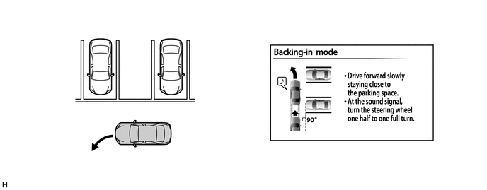
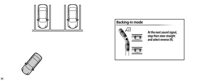
Pre-support Function Operation (Parking Assist Mode (Perpendicular Parking))
-
Press the parking assist pre support switch assembly twice with the vehicle positioned before the parking space.
-
When the pre-support function screen is displayed, drive forward slowly.
-
When the tone is heard, turn the steering wheel while driving.
-
When the tone is heard again, stop the vehicle.
-
Return the steering wheel and move the shift lever to R to change to the parking space display.
-
-
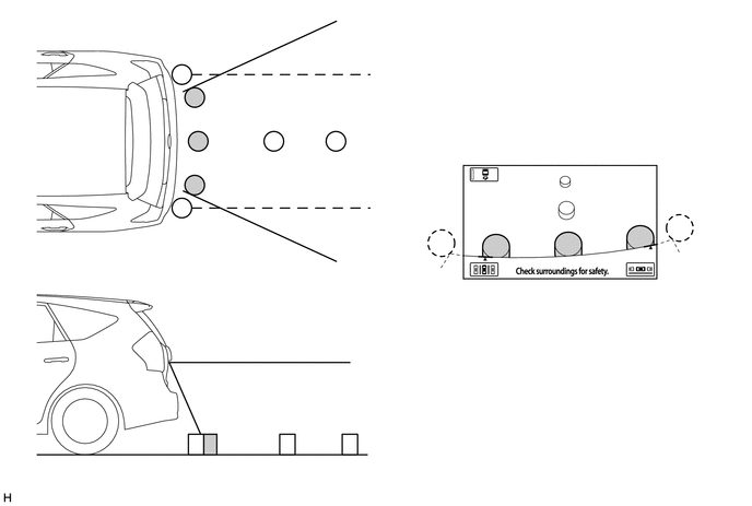
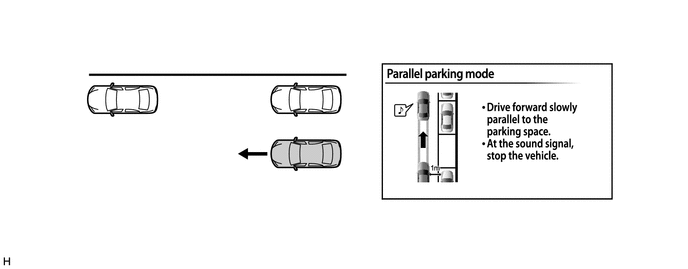
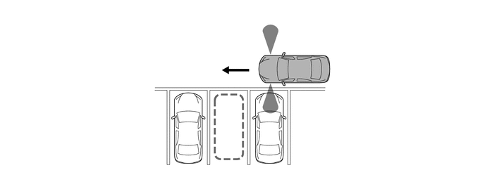
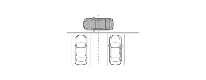
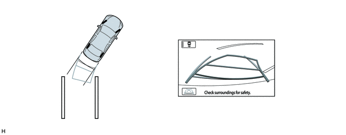
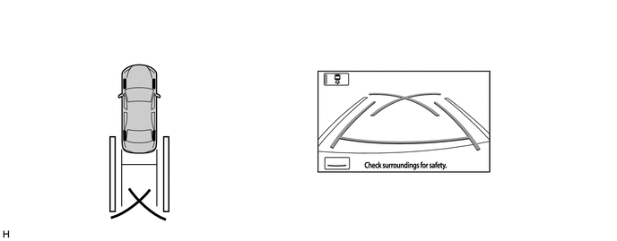
Parallel Parking Assist Mode Operation
-
Move the vehicle to a position parallel to the road (or shoulder) and approximately 1 m (3.3 ft.) away from the parked vehicles.
-
At this time, the No. 1 ultrasonic sensors mounted on both sides of the front bumper start detecting the distance between the driven vehicle and the parked vehicle to calculate the parking space.

Text in Illustration *a Approximately 1 m (3.3 ft.) - - -
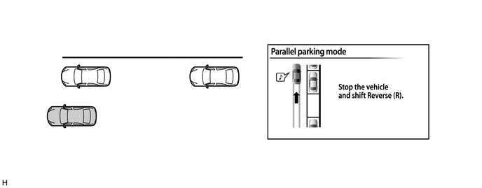
Slowly move the vehicle forward parallel to the parking space with the steering wheel straight. Stop the vehicle where you can see the front end of the parked vehicle right beside your vehicle.

-
Move the shift lever to R.
-
Touch the parallel parking assist switch on the screen.

-
Use the arrows to align the blue frame with your target parking position, and touch the OK switch.

-
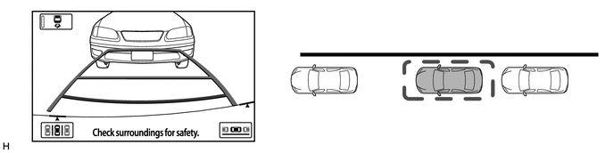
Position yourself as you would when backing up normally, and rest your hands on the steering wheel without applying any pressure. Check your surroundings and behind the vehicle for safety, and slowly back up, using the brake pedal to control the vehicle speed.
-
At this time, the messages, "Check surroundings for safety." and "Stop vehicle by using foot brake." are alternately displayed on the warning message display area on the screen.

-
Once the vehicle is mostly within the target parking position, voice guidance will give the message "The guidance is finished", and parallel parking assist mode will finish.
-
-
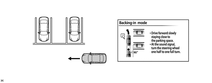
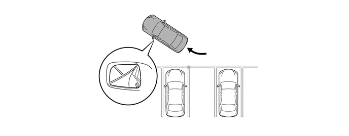
Parking Assist Mode (Perpendicular Parking) Operation
-
Move the vehicle to a position perpendicular to the parking space, and as close as possible to the parked vehicle.
-
At this time, the ultrasonic sensors mounted on both sides of the front bumper start detecting the distance between the driven vehicle and the parked vehicle to calculate the parking space.
-
Move the vehicle to a position where you can see the center of the parking space just beside your vehicle, and start turning the steering wheel.
-
Position the vehicle so that you can enter the parking space, then stop the vehicle with the steering wheel straight.
-
At this time, when you position the vehicle where a corner of the parking space is reflected in the center of the outside rear view mirror, you can easily adjust the target parking space.
-
Move the shift lever to R.
-
Touch the parking assist mode switch displayed on the screen.

-
Touch the arrows to align the blue frame with the target parking position, and then touch the OK switch.

-
Position yourself as you would when backing up normally, and rest your hands on the steering wheel without applying any pressure. Check your surroundings and behind the vehicle for safety, and slowly back up, using the brake pedal to control the vehicle speed.
-
At this time, the messages, "Check surroundings for safety." and "Stop vehicle by using foot brake." are alternately displayed on the warning message display area on the screen.

-
Once the vehicle is mostly within the target parking position, voice guidance will give the message "The guidance is finished," and parking assist mode will end.
-
-
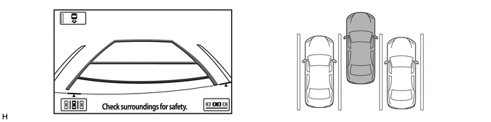
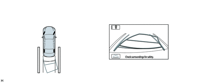
Estimated Guide Line Mode Operation
-
To use estimated guide line mode in manual assist when parking the vehicle in a parking space, perform the following procedure:
-
Move the shift lever to R.
-
An image appears on the display panel as illustrated below.
-
Turn the steering wheel so that the estimated guide lines are within the parking space, and back up carefully.
-
When the rear of the vehicle is within the parking space, turn the steering wheel in order to equalize the gap between the left and right sides of the vehicle width extension lines and the painted lines of the parking space.
-
When the vehicle width extension guide lines and the painted lines of the parking space are parallel, straighten the steering wheel and then carefully back up until the entire vehicle is within the parking space.
-
-
-
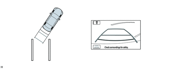
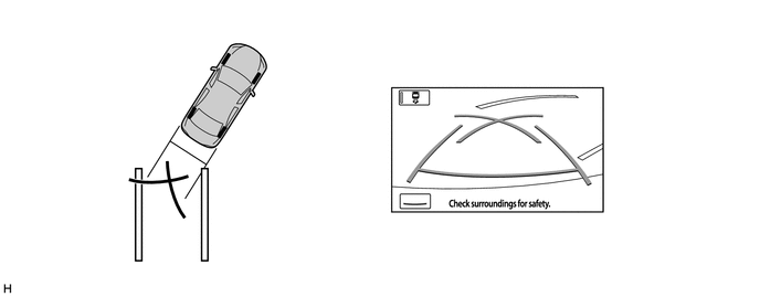
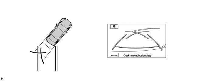
Parking Guide Line Mode Operation
-
To use parking guide line mode in manual assist when parking the vehicle in a parking space, perform the following procedure:
-
Move the shift lever to R.
-
Select parking guide line mode.
-
An image appears on the multi-display as illustrated below.
-
Back the vehicle and stop at the position in which the parking guide line comes in contact with the left side of the intended parking position.
-
Turn the steering wheel fully to the right and back the vehicle.
-
Continue backing the vehicle until the vehicle is parallel to the painted lines.
-
Once the vehicle is parallel, aim the steering wheel straight ahead and back the vehicle to the target stop position.
-
-
-
-
CONSTRUCTION
-
Rear Television Camera Assembly
-
The rear television camera assembly consists of a wide-angle lens and Charge Coupled Device (CCD) camera.
-
The image captured by the rear television camera assembly lens is converted into electrical signals according to the light intensity by using the CCD image element, and the signals are then output to the parking assist ECU.
-
The image output from the rear television camera assembly is reversed to match the rear view seen from the inner rear view mirror. Therefore, the rear view actually seen is displayed on the screen in a horizontally reversed form.

Text in Illustration *1 Wide-angle Lens - -
-
-
No. 1 Ultrasonic Sensor
-
The No. 1 ultrasonic sensor consists of a microphone that transmits and receives ultrasonic waves and a circuit portion.
-
The circuit portion is filled with urethane to prevent water from entering.
-
The No. 1 ultrasonic sensor integrates the connector in its housing. Also, a flat type microphone that has no concave edge is provided in order to improve the appearance.
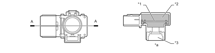
Text in Illustration *1 Circuit Portion *2 Urethane *3 Microphone - - *a A-A Cross Section - -
-
-
-
FAIL-SAFE
-
The table below indicates malfunction detection items for the sensors and ECUs in this system.
Malfunctioning Part Detection Item Function Rear Display Mode Parking Assist Mode (Perpendicular Parking) / Parallel Parking Assist Mode Spiral Cable with Sensor Sub-assembly
- Steering Angle Sensor
-
Transmission of sensor malfunction signal
-
Open circuit in sensor signal
-
Communication malfunction between the spiral cable with sensor sub-assembly (steering angle sensor) and parking assist ECU
Displays "Guidance unavailable." The mode automatically switches to rear display mode and the following message will appear on the screen: "Check IPA system. Have your vehicle checked by a dealer." Transmission of signal of incompletion of neutral steering point correction Displays "System initializing." The mode automatically switches to rear display mode and the following message will appear on the screen: "System initializing." Rear Television Camera Assembly Transmission of rear television camera assembly malfunction signal Stops signal reception and displays a dark screen Parking Assist ECU Malfunction of parking assist ECU Stops system operation Power Steering ECU Assembly Malfunction of power steering ECU assembly - The mode automatically switches to rear display mode and the following message will appear on the screen: " Check IPA system. Have your vehicle checked by a dealer." -
-
-
DIAGNOSIS
-
The navigation receiver assembly is equipped with a diagnosis function which can display a diagnosis menu for the intelligent parking assist system. For details, refer to the Repair Manual.
-